Download

1 / 60
610 likes | 888 Views
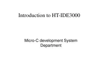
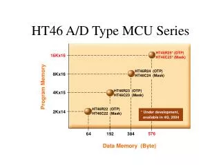
Introduction of Holtek HT-46 series MCU. Content. Family of A/D Type MCU 1. Cost-Effective A/D type MCU 2. A/D type MCU 3. A/D with LCD type MCU 4. A/D with VFD type MCU 5. A/D with OPA type MCU Detail of HT46R24 1. Features of HT46R24 2. Block Diagram

E N D
Content • Family of A/D Type MCU 1. Cost-Effective A/D type MCU 2. A/D type MCU 3. A/D with LCD type MCU 4. A/D with VFD type MCU 5. A/D with OPA type MCU • Detail of HT46R24 1. Features of HT46R24 2. Block Diagram 3. Function Description(ROM, RAM, Interrupt, I/O, Timer, Buzzer, Oscillator, ADC, I2C, PWM, ….)
Arithmetic ADD, SUB… Increment & Decrement INC, INCA, DEC… Logic Operation AND, OR, XOR… Rotate RR, RRC, RL… Data Move MOV… Bit operation SET, CLR… Table Read TABRDC, TABRDL Branch JMP, SZ, RET, RETI… Miscellaneous NOP, SWAP, HALT… 63 Instructions
IndirectAddressing • Indirect addressing Register: • IRA0,IRA1. • Memory Pointers: • MP0,MP1.
Interrupt • Interrupt has priority issue. • Once an interrupt subroutine is serviced, all the other interrupts will be block ( by cleaning the EMI flag). • After the subroutine set the “RETI”, the EMI will be set again.
3 modes available for the Timer/Counter • Timer Mode • Event Counter Mode • Pulse Width Mode
4 steps to setup in the Timer Mode • Set to Timer Mode by writing 10 to TM1, TM0 • Set the initial timer TMR value • Enable the corresponding interrupt by setting the ETI and EMI bit • Start the Timer by setting the TON bit of the TMRC
5 steps to setup in the Even Counter Mode • Set to Event Counter Mode by writing 01 to TM1, TM0 • Select TE=1 to count on the falling edge or TE=0 to count on the rising edge • Set the Timer initial value into TMR • Enable the corresponding interrupt by setting the ETI and EMI bits • Start the Timer by setting the TON bit in the TMRC register
5 steps to setup in the Pulse Width Measurement Mode • Set to Pulse Width Mode by writing 11 to TM1, TM0 • Select TE=1 to measure a High Pulse Width and TE=0 to measure a Low Pulse Width • Set the Timer initial value, TMR, usually set to 0H for Pulse Width Measurements • Enable the corresponding interrupt by setting the ETI and EMI bits • Start the Timer by setting the TON bit in the TMRC
PFD and Buzzer • PFD is programmable frequency divider. • PFD is pin shared with PA3(selected via configuration optional). • Clock source of PFD is come from timer0 or timer1 overflow signal (selected via configuration optional). • PFD output is controlled by switch on/off PA3.
Watchdog Timer • The watchdog timer is provided to prevent program uncontrollable . • 3 clock sources can be selected as watchdog timing source: (by configuration) • T1(fsys /4) , 32KHz RTC, WDT OSC output. • At HALT, only WDT OSC or RTC oscillator is still running.
Watchdog Register • If watchdog timeout ,the system will be reset. The status bit “TO” will be set. • There are two method of using software to clear watchdog timer (selected by configuration) : • One instruction : CLR WDT • Two instruction : CLR WDT1, CLR WDT2
PWM • PWM is Pulse Width Modulator. • There are two modes 6+2 or 7+1 selected by configuration. • User can change the duty cycle by software • by writing data to PWM0~PWM3 special data register. • PWM function can be controlled On/Off by software. • Enable PWM output : SET PD0 • Disable PWM output : CLR PD0
Analog to Digital Converter • The HT46R24 has a 10-bit ADC. • ADC can be disabled by software. • Max. 4 or 8 channels can input to the ADC. • Channels set in ADCR by software • ADC channels are pin-shared with Port B. • As ADC input or Port B set in ADCR by software • Input range is from 0 to VDD. • Min. ADC clock period is 1 us. • ADC sampling time is 32 ADC clocks. • ADC convert time is 76 ADC clocks. • Max. INL ± 1 LSB.
ADC Convert Data Register • ADRL/ADRH are two registers to store the ADC convert data.
I2C Bus Interface • I2C bus is a bidirectional 2-wire serial interface. • SCL : serial clock pin. • SDA : serial data pin. • I2C output is of open drain . An external pull high resistor is needed. • HT46 series I2C bus is only operates in Slave mode. For Master mode , user can implement by software.
I2C relative Registers • I2C Slave Address Register - HADR • I2C Input/Output Data Register – HDR • I2C Control Register –HCR. • I2C Status Register – HSR.
I2C Bus Communication • STEP1 • Write the slave address of the microcontroller to the HADR. • STEP2 • Set the HEN(bit7 of HCR) to 1 to enable the I2C bus. • STEP3 • Set the EHI(bit2 of INTC1) to 1 to enable I2C interrupt
HALT • The system oscillator will be turned off. • All of the I/O ports and RAM remain unchanged. • The WDT will be cleared and resume counting if the WDT clock source is selected to come from the WDT oscillator. • The PDF is set and the TO is cleared.