Download
1 / 22
260 likes | 697 Views
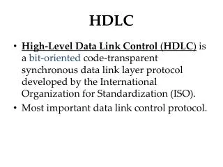
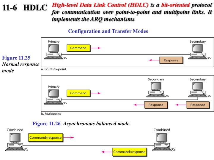
High-level Data Link Control (HDLC) is a bit-oriented protocol for communication over point-to-point and multipoint links. It implements the ARQ mechanisms. 11-6 HDLC. Configuration and Transfer Modes. Figure 11.25 Normal response mode. Figure 11.26 Asynchronous balanced mode.

E N D
High-level Data Link Control (HDLC) is a bit-oriented protocol for communication over point-to-point and multipoint links. It implements the ARQ mechanisms 11-6 HDLC Configuration and Transfer Modes Figure 11.25 Normal response mode Figure 11.26 Asynchronous balanced mode
Figure 11.27 HDLC frames Figure 11.28 Control field format for the different frame types
Flag Field It is an 8-bit sequence with a bit pattern of 01111110 Identify start and end of the frame Serve for the synchronization Bi stuffing is used to avoid the appearance of this number in that data Address field Address of the secondary station Whether the station is the originator or the destination If primary creates the frame it contains “to” otherwise “from” It can be 1 or several byte long Always the last bit ends with 1 If more than one byte all byte’s last bit ,except the last byte ,will end with 0. Ethernet does not use primary/secondary environment ,uses two address fields Sender address Receiver address Fields
Control Field 1 or 2 byte Used for error and flow control Interpretation is different for different frame types Information Field User’s data from the network layer or Network management information layer Length can vary but fixed for one network FCS Frame check sequence It contain 2 or 4 byte ITU-T CRC Fields
FRAME TYPES • I-frame • S-frame
Example 11.9 Figure 11.29 Example of connection and disconnection Figure 11.29 shows how U-frames can be used for connection establishment and connection release. Node A asks for a connection with a set asynchronous balanced mode (SABM) frame; node B gives a positive response with an unnumbered acknowledgment (UA) frame. After these two exchanges, data can be transferred between the two nodes (not shown in the figure). After data transfer, node A sends a DISC (disconnect) frame to release the connection; it is confirmed by node B responding with a UA (unnumbered acknowledgment).
Example 11.10 Figure 11.30 shows an exchange using piggybacking. Node A begins the exchange of information with an I-frame numbered 0 followed by another I-frame numbered 1. Node B piggybacks its acknowledgment of both frames onto an I-frame of its own. Node B’s first I-frame is also numbered 0 [N(S) field] and contains a 2 in its N(R) field, acknowledging the receipt of A’s frames 1 and 0 and indicating that it expects frame 2 to arrive next. Node B transmits its second and third I-frames (numbered 1 and 2) before accepting further frames from node A. Its N(R) information, therefore, has not changed: B frames 1 and 2 indicate that node B is still expecting A’s frame 2 to arrive next. Node A has sent all its data. Therefore, it cannot piggyback an acknowledgment onto an I-frame and sends an S-frame instead. The RR code indicates that A is still ready to receive. The number 3 in the N(R) field tells B that frames 0, 1, and 2 have all been accepted and that A is now expecting frame number 3.
Example 11.11 Figure 11.31 shows an exchange in which a frame is lost. Node B sends three data frames (0, 1, and 2), but frame 1 is lost. When node A receives frame 2, it discards it and sends a REJ frame for frame 1. Note that the protocol being used is Go-Back-N with the special use of an REJ frame as a NAK frame. The NAK frame does two things here: It confirms the receipt of frame 0 and declares that frame 1 and any following frames must be resent. Node B, after receiving the REJ frame, resends frames 1 and 2. Node A acknowledges the receipt by sending an RR frame (ACK) with acknowledgment number 3.
11-7 POINT-TO-POINT PROTOCOL Although HDLC is a general protocol that can be used for both point-to-point and multipoint configurations, one of the most common protocols for point-to-point access is the Point-to-Point Protocol (PPP). PPP is a byte-oriented protocol. Figure 11.32 PPP frame format PPP is a byte-oriented protocol using byte stuffing with the escape byte 01111101.
Figure 11.35 LCP packet encapsulated in a frame Table 11.2 LCP packets
Table 11.3 Common options Figure 11.36 PAP packets encapsulated in a PPP frame
Figure 11.38 IPCP packet encapsulated in PPP frame Table 11.4 Code value for IPCP packets
Figure 11.39 IP datagram encapsulated in a PPP frame Figure 11.40 Multilink PPP
Example 11.12 Let us go through the phases followed by a network layer packet as it is transmitted through a PPP connection. Figure 11.41 shows the steps. For simplicity, we assume unidirectional movement of data from the user site to the system site (such as sending an e-mail through an ISP). The first two frames show link establishment. We have chosen two options (not shown in the figure): using PAP for authentication and suppressing the address control fields. Frames 3 and 4 are for authentication. Frames 5 and 6 establish the network layer connection using IPCP. The next several frames show that some IP packets are encapsulated in the PPP frame. The system (receiver) may have been running several network layer protocols, but it knows that the incoming data must be delivered to the IP protocol because the NCP protocol used before the data transfer was IPCP. After data transfer, the user then terminates the data link connection, which is acknowledged by the system. Of course the user or the system could have chosen to terminate the network layer IPCP and keep the data link layer running if it wanted to run another NCP protocol.