Download
1 / 52
570 likes | 1.08k Views
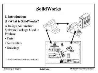
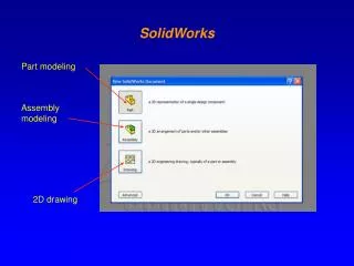
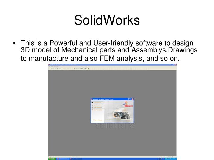
SolidWorks. This is a Powerful and User-friendly software to design 3D model of Mechanical parts and Assemblys,Drawings to manufacture and also FEM analysis, and so on. By click on New , 3 options will be appeared (Part, Assembly, and Drawing). Starting SolidWorks.

E N D
SolidWorks • This is a Powerful and User-friendly software to design 3D model of Mechanical parts and Assemblys,Drawings to manufacture and also FEM analysis, and so on.
By click on New, 3 options will be appeared (Part, Assembly, and Drawing) Starting SolidWorks
Every part is composed of a sketch and a feature 1- Go to Sketch Mode and Draw a 2D sketch(sketch is a drawing that it has no thickness like line, circle, rectangle, arc,… ) 2- Go to Feature Mode, select one of the appropriate commands to create 3D model(such as Cube, Cylinder, spring,…) Design a Part
Sketch Toolbar Feature Manager Tree Front Plane Creating a Sketch First choose a main plane from Feature manager Tree Select Sketch on the main toolbar 2-Click on Then choose the appropriate geometrical command from Sketch Toolbar
This box displays all the features of your part or assembly. It also lists planes, axis, and Mating groups. To select the main Planes(Front, Top, and Right) To modify and see the procedure of designing a part, it has a dynamic relation with area of drawing Feature Manager Tree
Sketch and Feature Toolbars • To create any Sketch (drawing ) use the sketch toolbar. • Feature Toolbar: this toolbar contains all the functions for creating and manipulating 3D shapes
Basic Feature functions http://www.dmti.unifi.it/dac_prato/modellazione/modelling.html
Click on Sketch Click on Creating a Part First: Sketch
Choose one of the Main planes to draw the Sketch (Hint:Before creating a sketch you should choose a Plane or a side of part) Creating a Part
After selecting one of the main plane, click on a shape on Sketch Toolbar(Rectangle) Now, by clicking on the design area and move the pointer you can draw the sketch 2D Sketch
Use Dimension Tool(click on Smart Dimesion) Select the entities to add the dimensions Double click on dimensions to modify the dimensions Adding Dimensions
It is not required to add dimension on sketch before use them to create a feature FullyDefiend Sketch: the position of all entities are fully described, and all the entities are BLACK UnderDefined Sketch: additional dimensions or relations are needed to completely specify the geometry, under defiened entities are BLUE Over Defiened Sketch, an object has conflicting dimensions or relations, or both. Over defined entities are RED. Over defined Sketch Dimensions
Feature mode • Now the feature toolbar will be activated • Now by clicking on Features on the main Toolbar, switch to Feature mode
Extrude • Extrude the sketch • 1-click Extruded base • 2-Set End Condition to Blind • 3-Set Depth to 10 mm • Click OK.
Extruded Cut Select a side of part as a plane to draw the sketch (by clicking on it)
Draw the sketch • Click on Sketch • Click on Rectangle • Draw it on the selected plane
Extruded Cut • Click on Feature • Click on Extruded cut (the preview)
Cut-Extrude • From the Cut-Extrude Menu Choose the Through All
In sketch mode Select Front Plane in Feature manager Draw the path for ex. By clicking spline draw like the picture Sweep(first create the path)to move a profile along a Path
Now draw another sketch as the X-section: Choose the Top plane Draw the profile in sketch mode (cirlce) Sweep(create the x-section)
Click Insert Choose Reference Geometry 1-Plane Parallel plane Normal to curve plane 2-Axis 3-… Reference Geometry
a plane parallel to the Front Plane with a distance 10 mm Reference geometry
Drawing the circle of spring Curve>Helix Defining the plane Normal to Curve Drawing the circle Sweep Now a complex exampleCreating a Spring by Sweep
Drawing a Helix Curve • First Step Draw the sketch of circle in one of the main plane
Drawing the Helix Curve • Click on Curve command • Select Helix • Define the Pitch and Revolution
Define a perpendicular plane to one end of the helix curve • Choose one of the end point of Helix • Insert> Ref. Geometry>plane • Normal to curve(select the curve and an end point)
Drawing the x-section • In the defined plane, click on sketch • Select Circle and draw it (put the center of circle on the end point of curve)
Swept • Now click on Feature to go to the feature mode • then Click on Swept Boss/ Base
Sweep • In the sweep menu click on the profile box • Select the circle as the profile • Select the helix curve as the path
Edit Sketches and Features • From the Feature Manager Tree • Right click on each feature select Edit Feature or Edit Sketch
Viewing the Part: • You can access the standard engineering views by clicking the Standard Views button on the main toolbar: • Each small box on the "Standard View" menu corresponds to a view of the object. The best way to understand what each view means is to click each view and see what happens.
Assembly • Open a new assembly file(click on New>Assembly) • Insert the created • By clicking Mate , make the necessary relation between the parts • Save the assembly (with extension .asm or sldasm)
Assembly • Insert Components • Select Existing Part
Insert Parts From the box Browse and select the created parts to insert into assembly area
To make the assembly use the appropriateMate commands, -Coincident -Parallel -Tangent,…. Mate
Click on Mate Select the First face Use zoom and move or rotate to select the faces Mate (Coincident)
Select the Second face Solidworks automatically makes the selected faces coincident Mate(Coincident)
Click on mate Select the hole and shaft of the Two components Click on Concentric Mate (Concentric)
Save as • The assembly files should be save as with extention .asm, .sldasm
To imports the file in different softwares Solidworks provide you to save the files in appropriate format such as Ansys(.igs), Catia, …and Rapid protoype machine(.stl) Save(output)
Save the Assembly in stl format • During Save as, click on Options, • Choose (save all components of an assembly in a single file)