Download
1 / 49
490 likes | 637 Views
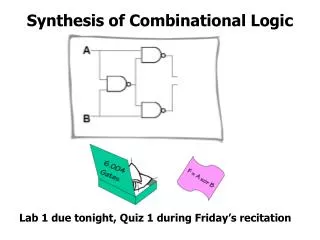
Function of Combinational Logic. DNT 231. Chapter Objectives. Distinguish between half-adder and full-adder Use BCD-to-7-segment decoders in display systems Apply multiplexer in data selection Use decoders as multiplexer ….. and more…. Basic Adder.

E N D
Function of Combinational Logic DNT 231
Chapter Objectives • Distinguish between half-adder and full-adder • Use BCD-to-7-segment decoders in display systems • Apply multiplexer in data selection • Use decoders as multiplexer • ….. and more…
Basic Adder Adder are important in computers and also in other types of digital systems in which numerical data are processed The half-adder accepts two binary digits on its inputs and produces two binary digits on its outputs, a sum bit and a carry bit Definition:
0 + 0 = 0 0 + 1 = 1 1 + 0 = 1 1 + 1 = 10 Zero plus zero equals zero Zero plus one equals one One plus zero equals one One plus one equals zero with a carry of one Simple Binary Addition Half-Adder
Half-Adder Logic Combinational Logic
The Full-Adder The Full-Adder accepts two input bits and an input carry and generates a sum output and an output carry Definition: The basic different between a full-adder and a half-adder is that the full-adder accepts an input carry.
The full-adder must add the two input bits and the input carry. From the half-adder, the sum of the input bits A and B is the exclusive-OR of those two variables. For the input carry (Cin) to be added to the input bits, it must be exclusive-ORed, and last yield the equation for the sum output of the full-adder
This is mean that to implement the full-adder sum function, two 2-input exclusive-OR gates can be used . The first must generate the term AB and the second has as its inputs the output of the first XOR gate and the input carry. The output carry is a 1 when both inputs to the first XOR gate are 1s or when both inputs to the second XOR gate are 1s. The output carry of full-adder is therefore produced by the inputs A ANDed with B and AB ANDed with Cin.
Example: Determine the outputs for the inputs shown 0 1 0 1 1 0 If A = 1, B = 1 and Cin = 1 ???? Σ = 0 Cout = 1
Parallel Binary Adder A single full-adder is capable of adding two 1-bit numbers and an input carry. To add binary numbers with more than one bit, we must use additional full-adders. 1 bit – 1FA 2 bit – 2FA 3 bit – 3FA 4 bit – 4FA ..and so on..
Example: Determine the sum generated by the 3-bit parallel adder 0
Four-Bit Parallel Adders 4-Bits – Nibble
Truth Table for a 4-Bit Parallel Adder Example: Use the 4-bit parallel adder truth table to find the sum and output carry for the following two 4-bit numbers if the input carry (Cn-1) is 0. A4A3A2A1 = 1100, B4B3B2B1 = 1100
11000 Solution: n=1, A1 = 0, B1 = 0 and Cn-1 = 0 Σ1 = 0 and C1 = 0 n=2, A2 = 0, B2 = 0 and Cn-1 = 0 Σ2 = 0 and C2 = 0 Σ3 = 0 and C3 = 1 n=3, A3 = 1, B3 = 1 and Cn-1 = 0 n=4, A4 = 1, B4 = 1 and Cn-1 = 1 Σ4 = 1 and C4 = 1 Try This! 1011 add with 1010 and Assume Cn-1 = 0 10101
Adder Expansion 8-Bits 16-Bits
Example: Show how two 74LS283 adders can be connected to form an 8-bit parallel adder. Show output bits for the following 8-bit input numbers:A8A7A6A5A4A3A2A1 = 10111001 and B8B7B6B5B4B3B2B1 = 10011110 Answer: Σ8Σ7Σ6Σ5Σ4Σ3Σ2Σ1 = 101010111
Comparators The basic function of a comparator is to compare the magnitude of two binary quantities to determine the relationship of those quantities • 1-Bit Comparator • 2-Bit Comparator • 4-Bit Comparator
1-Bit Comparator The output is 1 when the inputs are equal • 2-Bit Comparator The output is 1 when A0 = B0 AND A1 = B1
4-Bit Comparator • One of three outputs will be HIGH: • A greater than B (A > B) • A equal to B (A = B) • A less than B (A < B) • To determine an inequality of binary numbers A and B,first • the highest order bit in each number. The following • conditions are possible: • If A3 = 1 and B3 = 0, number A is greater than number B • If A3 = 0 and B3 = 1, number A is less than number B • If A3 = B3 then you must examine the next lower bit position for an inequality
Example:Determine the A = B, A > B and A < B outputs for the input numbers shown on Figure below: A > B is HIGH and the other outputs are LOW Try This: A3A2A1A0 B3B2B1B0 1 0 0 1 1 0 1 0 A < B is HIGH and the other outputs are LOW Try This: A3A2A1A0 B3B2B1B0 1 0 1 1 1 0 1 0
Decoders • Decoder is a digital circuit that converts coded information into a familiar or non coded form. • Binary decoder • 4-bit decoder • BCD-to-decimal decoder • BCD-to-7-segment decoder
Binary decoder • The output is 1 only when: • A0 = 1 • A2 = 0 • A3 = 0 • A4 = 1 The output is only what we want! This is only one of an infinite number of examples
Determine the logic required to decode the binary number 1011 by producing a HIGH level on the output Example: Try This: Develop the logic required for 10010 and produce an active LOW output Solution:
The 4-Bit Decoder In order to decode all possible combinations of 4-bits, sixteen gates are required (24 = 16). This type of decoder is commonly called either 4-line-to-16-line decoder or 1-of-16 decoder. Truth Table Output is Active Low
The 74HC154 1-of-16 Decoder The IC will active if gate output (EN) is HIGH If /CS1 and /CS2 are LOW, so EN will HIGH and IC is active!
Example:A certain application requires that a 5-bit number be decoded. Use 74HC154 decoders to implement the logic. The binary number is represented by the format A4A3A2A1A0. Determine the output in Figure that is activated for the binary input 1 0 1 1 0 ? Answer: 22 Disable Enable Disable Enable 1 0 1 0
The BCD-to-Decimal Decoder The BCD-to-decimal converts each BCD code into one of ten possible decimal digit indications. It is frequently referred as 4-line-to-10- line decoder or a 1-of-10 decoder. The method of implementation is the same as for the 1-of-16 decoder.
Example:The 74HC42 is an integrated circuit BCD-to-decimal decoder. The logic symbol is shown in Figure 1 below. If the input waveforms in Figure 2 are applied to the inputs of the 74HC42, show the output waveforms. 0 1 0 1 0 1 0 1 0 1 0 01 1 0 0 1 1 0 0 0 00 0 1 1 1 1 0 0 0 00 0 0 0 0 0 1 1
Exercise:Construct a timing diagram showing input and output waveforms for the case where the BCD inputs sequence thru’ the decimal numbers as follows: 0, 2, 4, 6, 8, 1, 3, 5 and 9
The BCD-to-7 Segment Decoder The BCD-to-7-segment decoder accepts the BCD code on its inputs and drive 7-segment display devices to produce a decimal readout.
Encoders • Decimal-to-BCD encoder • 8-line-to-3-line encoder An encoder is a combinational logic circuit that essentially performs a “reverse” decoder function.
Multiplexer (Data Selectors) • A multiplexer (MUX) is a device that allows digital information from several sources to be routed onto a single line for transmission over that line to a common destination. • The basic multiplexer has several data-input lines and a single output line. • It also has data-select inputs, which permit digital data on any one of the inputs to be switched to the output line.
Example:Determine the output waveform in relation to the inputs
Exercise: Determine the output waveform in relation to the inputs
Multiplexer • Larger multiplexers can be constructed from smaller ones. • An 8-to-1 multiplexer can be constructed from smaller multiplexers as shown:
Demultiplexers • A demultiplexer (DEMUX) basically reverses the multiplexing function. • It takes digital information from one line and distributes it to a given number of output lines.
1-to-4 DEMUX D3 Example: Data Input = 1 and S1 and S0 = 1
1-line-to-8-line multiplexer 1-to-8 DEMUX
Mux-Demux Application Example This enables sharing a single communication line among a number of devices. At any time, only one source and one destination can use the communication line.