Collaboration Diagrams in CSIS3600 Course
330 likes | 367 Views
Collaboration diagrams illustrate interactions between objects, representing messages sent between classes and objects. They visualize relationships and interaction among collaborating objects, aiding in task performance understanding. Learn about elements, syntax, and flow of messages in collaboration diagrams.

Collaboration Diagrams in CSIS3600 Course
E N D
Presentation Transcript
Collaboration Diagrams CSIS3600
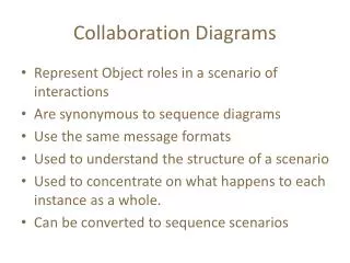
What is a Collaboration Diagram • Collaboration diagrams illustrate interactions between objects • The collaboration diagram illustrates messages being sent between classes and objects (instances). • Collaboration diagrams express both the context of a group of objects (through objects and links) and the interaction between these objects (by representing message broadcasts)
Purpose of the Collaboration Diagram • They are very useful for visualizing the relationship between objects collaborating to perform a particular task • They provide a good view – albeit static - view of interaction between objects which may be difficult to see at the class level
Collaboration Diagram • Represents a Collaboration and Interaction • Collaborationset of objects and their interactions in a specific context • Interactionset of messages exchanged in a collaboration to produce a desired result
Collaboration Diagram Elements • There are three primary elements of a collaboration diagram: • Objects • Links • Messages
aMessage() Collaboration Diagram Syntax AN ACTOR AN OBJECT AN ASSOCIATION A MESSAGE anObject:aClass
Objects • Objectsrectangles containing the object signatureobject signature: • object name : object Class • object name (optional) - starts with lowercase letter • class name (mandatory) - starts with uppercase letter • Objects connected by linesactor can appear
Objects • Objects participating in a collaboration come in two flavors—supplier and client • Supplier objects are the objects that supply the method that is being called, and therefore receive the message • Client objects call methods on supplier objects, and therefore send messages
Transaction object acts as a Supplier to the UI (User Interface) Client object. In turn, the Fine object is a Supplier to the Transaction Client object.
Links • The connecting lines drawn between objects are links • They enable you to see the relationships between objects • This symbolizes the ability of objects to send messages to each other • A single link can support one or more messages sent between objects
The visual representation of a link is a straight line between two objects. If an object sends messages to itself, the link carrying these messages is represented as a loop icon. This loop can be seen on both the UI object and the Transaction object.
Messages • An interaction is implemented by a group of objects that collaborate by exchanging messages • Messages in collaboration diagrams are shown as arrows pointing from the Client object to the Supplier object. • Typically, messages represent a client invoking an operation on a supplier object
Messages • Message icons have one or more messages associated with them • Messages are composed of message text prefixed by a sequence number • Time is not represented explicitly in a collaboration diagram, and as a result the various messages are numbered to indicate the sending order
Flow by Numbers 1. Enter Borrower ID 1.1 CalcAmtCanBorrow 1.1.1 <<create>> 1.1.2 CalcBorrowerFines 1.1.3 GetBorrowersCheckedOutMedia 1.1.4 IsMediaOverdue 1.1.5 Amt Can Borrow 1.2 Display Invalid User Msg
Message Flow Notation Same as for sequence diagrams Synchronous Flow of control Asynchronous Return
Iterating Messages • Collaboration diagrams use syntax similar to sequence diagrams to indicate that either a message iterates (is run multiple times) or is run conditionally • An asterisk (*) indicates that a message runs more than once • Or the number of times a message is repeated can be shown by numbers (for example, 1..5)
Conditional Messages • To indicate that a message is run conditionally, prefix the message sequence number with a conditional [guard] clause in brackets [ x = true ]: [IsMediaOverdue] • This indicates that the message is sent only if the condition is met
Collaboration vs Sequence Diagram • In reality, sequence diagrams and collaboration diagrams show the same information, but just present it differently • Not used as often as sequence diagrams but are closely related
Collaboration diagram is better at showing the relationship between objects
Number of Messages • In sequence diagrams, each message icon represents a single message. • In collaboration diagrams, a message icon can represent one or more messages. • Noticebetween the Transaction and Fine objects - there is a single message icon, but there are two messages (1.1.1 and 1.1.2) associated with the icon.
Collaboration and Class Diagrams • Links in a collaboration diagram directly correlate to associations between classes in a class diagram
Steps to Creating a Collaboration Diagram • Determine the scope of the diagram- the use case it relates to • Place the objects that participate in the collaboration on the diagram • Remember to place the most important objects towards the center of the diagram. • If a particular object has a property or maintains a state that is important to the collaboration, set the initial value of the property or state
Steps to Creating a Collaboration Diagram • Create links between the objects • Create messages associated with each link • Add sequence numbers to each message corresponding to the time-ordering of messages in the collaboration
Creation and Deletion • Unlike sequence diagrams, you don't show an object's lifeline in a collaboration diagram • If you want to indicate the lifespan of an object in a collaboration diagram, you can use create and destroy messages to show when an object is instantiated and destroyed
Objects Changing State • State of on object can be indicated • Initial state is indicated with <<create>> • If an object changes significantly during an interaction, you can add a new instance of the object to the diagram, draw a link between them and add a message with the stereotype <<become>>
Reference • http://www.devx.com/codemag/articles/2002/mayjune/collaborationdiagrams/codemag-2.asp