Download
1 / 14
150 likes | 170 Views
Engineering Modeling: Mathematical and Computer. What is Engineering Modeling?. Model : A representation of a real object or system of objects for purposes of visualizing its appearance or analyzing its behavior.

E N D
What is Engineering Modeling? Model: A representation of a real object or system of objects for purposes of visualizing its appearance or analyzing its behavior. Simulation: Transition from a mathematical or computer model to a kinematics description (motion) of the system behavior based on sets of input parameters.
Engineering Modeling and Simulation Versus Experimentation Experimentation might not be feasible due to: • inaccessible inputs and outputs. • experiment may be too dangerous. • cost of experimentation might be too high. • time constants of the system may not be compatible with human dimensions. • experimental behavior might be obscured by disturbances.
Types of Models • Visual models to simulate form and appearance: graphical sketches, computer solid models. • Physical models to simulate function: prototypes, mock-ups, structural models. • Mathematical/Computational models to simulate function: algebraic and/or differential equations used for computer simulations. • Empirical models to simulate function: relationships between variables established by direct measurement (equations, charts, or tables).
Physical Principles in Mathematical Modeling • Newton's Laws: • Equation of static equilibrium • Equation of dynamic equilibrium (motion) • Action-Reaction: • Conservation of energy • Conservation of momentum • Constitutive relations: • friction constants and relations (force vs. normal) • material constants and relations (stress vs. strain)
Observations: When fired, the spring releases all of its energy to the gun top and projectile. The projectile then transfers rotational energy to translational energy in two ways: 1) through an impulse on the projectile when the gun stops moving; and 2) during flight, through aerodynamic lift and drag.
Equations of Motion: Mathematical Model Sum of the forces in the vertical direction: Sum of moments about the center of mass of the projectile:
Fn includes drag and lift on the blade. Drag: resistance to air (function of velocity, density, area, and shape); opposes the motion. Lift: a function of the pressure difference between top and bottom of the blade (e.g., airplanes wings) provided by high speeds, and the surface area of the blade. It should exceed the weight to rise (e.g., helicopters).
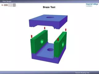
3-D Geometric Computer Models • Applications • Design Visualization • Design Analysis • Design Simulation • 3-D Section Views • .STL Files for Prototyping • Generate 2-D Drawings
Example Project Analysis -------------- SOLIDS ----------- Mass: 2.5164 Volume: 2.5164 Bounding box: X: 1.7000 - 4.3000 Y: 1.7000 - 4.3000 Z: -1.2000 - 0.8349 Centroid: X: 3.0000 Y: 3.0000 Z: 0.2233 Moments of inertia: X: 23.9782 Y: 24.0982 Z: 47.3818 Products of inertia: XY: 22.6474 YZ: 1.6856 ZX: 1.6856 Radii of gyration: X: 3.0869 Y: 3.0946 Z: 4.3393
Computer Solid Modeling • Build a Computer Solid Model of Each Individual Part. • Make an Assembly Model of all Your parts. • Make a Shaded Color Hardcopy of Each Part and the Assembly. • Make a Mass Properties Analysis Report of Each Part. • Make an .STL File of Each Part (for later use) Save Your Files!