Download
1 / 33
330 likes | 335 Views
Positioning Chapter 8. TexPoint fonts used in EMF. Read the TexPoint manual before you delete this box.: A A A A A A A A. Lecturer: Rainer Mautz. Geodetic Metrology and Engineering Geodesy Institute of Geodesy & Photogrammetry, ETH Zurich

E N D
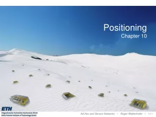
PositioningChapter 8 TexPoint fonts used in EMF. Read the TexPoint manual before you delete this box.: AAAAAAAA
Lecturer: Rainer Mautz Geodetic Metrology and Engineering Geodesy Institute of Geodesy & Photogrammetry, ETH Zurich HIL D43.2, Hönggerberg, Wolfgang-Pauli-Str. 15, CH-8093 Zurich +41 44 633 24 85 http://www.geometh.ethz.ch/people/rmautz
GPS WLAN Application: Natural Hazards Monitoring (e.g. Volcanos) • Stratovolcano Sakurajima, • island 77 km2 1117 m height • extremely active, densely populated • monitored with levelling, EDM, GPS Volcanoes experience pre-eruption surface deformation Coverage: cm – dm over 10 km2 Spatially distributed monitoring for early warning system WLAN positioning system with densely deployed location aware nodes Landsat image, created by NASA
Rating • Area maturity • Practical importance • Theoretical importance First steps Text book No apps Mission critical Not really Must have Sensor data without position information are normally worthless
Overview • Sensor Types • Positioning Systems • Methods for Positioning
User Requirements: dynamic all environments: indoors: household, office & factory outdoors: urban & rural availability: 100% of the time timeliness: realtime reliability: no failures hybrid systems: to be avoided local installations: none accuracy: mm - cm coverage: global
Classification of Positioning Systems: • Principle (trilateration, triangulation, signal strength) • Signal (Radio Frequencies, Light Waves, Ultrasound, RFID, Terahertz) • Environment (indoor, outdoor, urban, rural, remote) • Active / passive sensors • Accuracy (μm – km) • Application (industry, surveying, navigation)
Sensors used in Geodetic Networks • optical sensors (motorised total station, digital level) • GNSS sensors (that allow phase measurements) • geotechnical sensors (relative measurements using extensometer, inclinometer, plumbing, DMS, hydrostatic levelling) • meteo sensors (thermometer, pressure sensor, air moisture sensor) • key aspects & issues: • physical dimensions of the sensor (size, weight) • additional devices for data collection • format of generated data • measurement rate • connection to computer network • electrical power consumption and voltage • price
Positioning Sensors 1. optical sensors – motorised total stations S6/8 not yet specialised for that purpose (still can be used manually) problems: sensitive electronic, optical sight (fog), price, need for prisms
Totalstation Network automatic total station: a 1-node monitoring network from: Heunecke, Geosensornetze im Umfeld der Ingenieurvermessung
Positioning Sensors 1. optical sensors – motorised total stations Mt.Terri Felslabor - Messeinsatz – Stephan Schütz
Sensors used in Engineering Geodesy Networks 1. optical sensors – digital levels • restricted to 40 m and horizontal views • restricted to monitor a single staff
Sensors used in Engineering Geodesy Networks 2. GNSS sensors – handheld & geodetic receivers Why do geodetic receivers reach mm-accuracy?
Sensors used in Engineering Geodesy Networks • Use of both frequencies L1& L2 • Phase measurements • DGPS (relative measurements) elimination of ionospheric delays from: WIDE University (School of Internet) http://www.soi.wide.ad.jp/class/20050026/slides/01
GNSS Attenuation of building materials (L1 = 1500 MHz) Stone (1997) Signal Strength in Decibel Watt of GNSS Satellites
Sensors used in Engineering Geodesy Networks 3. Geotechnical Sensors • only one-dimensional, mostly local, relative measurements • high effort for installation (cables, adaption to the object, e.g. plumbing shafts, inclinometer pipes) • analogue signals A/D converter, logging unit
Sensors used in Engineering Geodesy Networks 4. Meteorological Sensors Meteo-Station WS-2308: T, p, wind direction, wind speed, participation, time reference using DCF-77 Mainflingen important for correction of other sensors
Sensors used in Engineering Geodesy Networks 5. Digital Cameras • IP-Camera NC 1000-W10: • detection of movements, • usable in the night • WLAN capability • detection of sounds IP-camera has its own IP-address. It can be used as a webcam that does not require a direct connection to a computer Cameras will play a more important role!
Positioning (Localization) Task: Given distance or angle measurements or mere connectivity information, find the locations of the sensors Anchor-based Some nodes know their locations, either by a GPS or as pre-specified. Anchor-free Relative location only. Sometimes called virtual coordinates. Theoretically cleaner model (less parameters, such as anchor density) Range-based Use range information (distance or angle estimation). Range-free No distance estimation, use connectivity information such as hop count. It was shown that bad measurements don’t help a lot anyway.
Measurement Methods for Positioning Angle estimation Angle of Arrival (AoA) Determining the direction of propagation of a radio-frequency wave incident on an antenna array. Distance estimation Received Signal Strength Indicator (RSSI) The further away, the weaker the received signal. Time of Arrival (ToA) or Time Difference of Arrival (TDoA) Signal propagation time translates to distance. RF, acoustic, infrared and ultrasound.
Positioning Based on Range Measurements Initialanchor Step1: becomesanchor becomes anchor Step 2: Step 3: becomesanchor Lateration Methods Multilateration: Iterative Multilateration: Collaborative (n-hop) Multilateration:
Ambiguity problem when creating the smallest rigid structure Positioning Based on Range Measurements
Positioning Based on Range Measurements • Solving flip ambiguity in the presence of noise
Positioning Based on Range Measurements • Expansion of a rigid structure by multilateration
AoA Measurement: iGPS iGPS transmitter and sensor during a test in a tunnel
AoA Measurements: iGPS “laser resection” • Key design: • two or more fixed transmitters • rotating fan-shaped laser beams • infrared signal • various sensors detect arrival times • position determination with spatial forward intersection graphic from Metris
Alternative Positioning Systems Locata: Terrestrial pseudolite transceivers Picture from Barnes et al. (2003) 6thIinternational Symposium on Satellite Navigation Technology , Melbourne, Australia
Locata – Key Parameters: (+) RTK: 1 – 2 cm deviations at 2.4 m/s (+) signal magnitude stronger than GNSS (+) indoors dm Problem: multipath (low elevation) Picture from J. Barnes, C. Rizos, M. Kanli, A. Pahwa „A Positioning Technology for Classically Difficult GNSS Environments from Locata“, IEEE Conference, San Diego California, 26 April 2006
Cambridge University TDoA: Ultrasound Systems – Crickets, Active Bat, Dolphin
TDoA: Ultrasound Systems – Crickets, Active Bat, Dolphin • Problems: • dependency on temperature • maximal range • deployment of reference beacons • multipath • reliability • interference with other sound sources
Positioning based on Signal Strength • All signals can be used: • WLAN, Ultrasound, RF, GPRS, etc. • Problems: • reliability • accuracy USC Robotics Research Lab RSSI in sensor networks: not for geodetic (reliable, precise) applications!
Auto-Positioning Algorithm Ceiling Beacons (static) Listener (moving) • Mobile listener collects distance measurements • redundancy = R – 3(B + P) + 6, • R = observed ranges, B = fixed beacons P = listener positions • Example below: redundancy = 0 (R = 24, B = 4, P = 6)