Download
1 / 36
360 likes | 488 Views
Anthony Colaprete and the LCROSS Team. LCROSS Mission Selection. LCROSS mission was selected on 4/10/06, via an ESMD two-step AO Step 1: Proposal generation (Pre-Phase A formulation phase) Step 2: Down-select of field of (19) proposals to (4) (Phase A formulation phase)

E N D
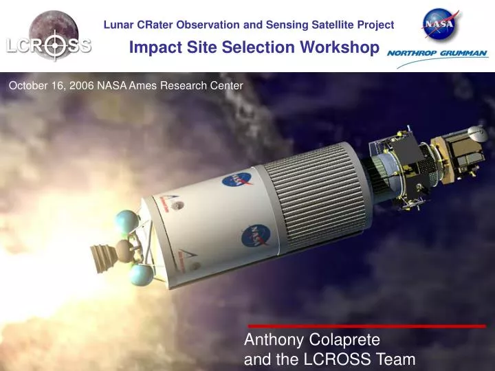
Anthony Colaprete and the LCROSS Team
LCROSS Mission Selection • LCROSS mission was selected on 4/10/06, via an ESMD two-step AO • Step 1: Proposal generation • (Pre-Phase A formulation phase) • Step 2: Down-select of field of (19) proposals to (4) • (Phase A formulation phase) • Step 3: Selection of LCROSS proposal • (Phase B entrance)
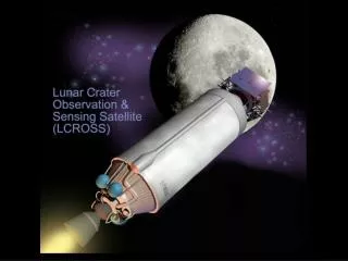
LCROSS Mission Overview • The LCROSS Mission is a Lunar Kinetic Impactor employed to reveal the presence & nature of water ice on the Moon • LCROSS Shepherding S/C (S-S/C) directs the 2000[kg] (4410[lb]) Centaur into a permanently-shadowed crater at 2.5[km/s] (1.56 [miles/s]) • ~200 metric tons (220 tons) minimum of regolith will be excavated, leaving a crater the size of ~1/3 of a football field, ~15 feet deep. • The S-S/C decelerates, observing the Centaur ejecta cloud, and then enters the cloud using several instruments looking for water • The S-S/C itself then becomes a 700[kg] (1,543[lb]) 'impactor' as well • Lunar-orbital and Earth-based assets will also be able to study both clouds, (which may include LRO, Chandrayaan-1, HST, etc)
LCROSS Project Team • A fast, capable team: • ARC provides the overall project management, systems engineering, risk management, and SMA for the mission • Northrop-Grumman provides the S/C and S/C integration for this mission as well as launch systems integration support • ARC provides the Science, Payloads, and Mission Ops for this mission • ARC, JPL, and GSFC provides the Navigation and Mission Design role • JPL is providing DSN services • KSC/LM is providing Launch Vehicle services • JHU-APL is providing avionics environmental testing
LCROSS Science Team Tony Colaprete (ARC) Geoff Briggs (ARC) Kim Ennico (ARC) Diane Wooden (ARC) Jennifer Heldmann (SETI) Tony Ricco (Stanford) Luke Sollitt (NGST) Andy Christensen (NGST) Erik Asphaug (UCSC) Don Korycansky (UCSC) Peter Schultz (Brown) Principal Investigator Deputy Principal Investigator Payload Scientist Observations/Analysis Observation Coordinator NIR Spectrometers Imaging systems Science Requirements Impact Processes Impact Processes Impact Processes
Mission Measurement Objectives Clementine Mosaic - South Pole • The LCROSS mission rational: • The nature of lunar polar hydrogen is one of the most important drivers to the long term Exploration architecture • Need to understand Quantity, Form, and Distribution of the hydrogen • The lunar water resource can be estimated from a minimal number of “ground-truths” • Early and decisive information will aid future ESMD and LPRP missions • The LCROSS mission science goals: • Confirm the presence or absence of water ice in a permanently shadowed region on the Moon • Identify the form/state of hydrogen observed by at the lunar poles • Quantify, if present, the amount of water in the lunar regolith, with respect to hydrogen concentrations • Characterize the lunar regolith within a permanently shadowed crater on the Moon Neutron Map - South Pole (Elphic et al.)
Mission Timeline Pre-Launch Launch Transfer Centaur Handover To LCROSS Centaur Venting & Re-Target Pad Ops LV Ascent Park Orbit Coast LRO Inject/Sep TCM-3 Swing by Calibration [TCM-4] VIF Ops TCM-1 TCM-2 Checkout Day -1 Day 0 Day 1 Day 2 Day 3 Day 4 Day 5 Day 6 Day 7 Cruise [TCM-7] [TCM-5] TCM-10 [TCM-6] TCM-8 TCM-9 Day 76 Day 15 Day 36 Day 57 Day 64 Day 69 Impact and Data Collection Final Targeting Final TargetingBurn BrakingBurn DataCollection EDUSImpact S-S/CImpact EDUSSeparation TCM-11 Timp+ 10min Day 85 Timp– 6.5hrs T = 0 Timp– 2hrs Timp– 8hrs Timp– 7hrs Day 86
LCROSS Mission Animation ( Click green button to start QuickTime movie )
Prospecting for Water …using 6.5 Billion Joules • The Atlas Centaur Impact: • Mass: ~2000 kg • Velocity: 2.5 km/sec • Angle: ~75 degrees • Minimize false positives by controlling EDUS contamination • Total H/O bearing materials (e.g. LOX, H2, H2O in batteries) kept below reported and kept below 100 kg • Minimize false negatives by combining multiple detection methods Crater Diameter, Depth and Excavated Water (Assumes a 10 cm desiccated Layer with uniform water mixing below)
The Current Best Estimate Impact Model (CBEIM) CBEIM Crater Size • The CBIEM summarizes the results of numerous impact models / assessments. • Used as the base to drive mission design and instrument selection. • Efforts continue to refine the model with an update due December, 2006.
Montecarlo Study of Ejecta Mass Median Average Montecarlo study of ejecta mass: Simulation varied the crater radius (Rcrat), velocity function exponent (a), total mas (Me), and ejecta flight angle (q). (See LCROSS technical note “LCROSS ejecta dynamics–Monte Carlo model (09/16/06)“ for details)
2 km 5 km 10 km 15 km 25 km 35 km CBEIM and Sensitivity Studies Average Ejecta Curtain Characteristics – 1% water content
Stages of the Impact Process Simulation using the Ames Vertical Gun Range Ejecta Curtain Peter Schultz
Stages of the Impact Process AVGR Flash Lunar Flash • Impact Flash and Vapor Cloud • Visible Component: • Compaction / Intergrain Strain • t~0.1 sec • F~0.001-1 mW m-2 (r=1000 km) • NIR Component: • Blackbody Emission of Vapor Cloud • t~1 sec • F~0.01-10 mW m-2 (r=1000 km) • Total energy sensitive to target properties such as material strength, density and water content. • Shape of the curve reflects the penetration depth, changes in material competence • A variety of visible and NIR spectral emissions relate to composition of target material and the fraction of the impactor which vaporizes Flash Brightness vs Time
Stages of the Impact Process • Ejecta Curtain Evolution • After the flash, target material is ejected outward on ballistic trajectories. • Visible Component: • Curtain illuminated by sunlight • Spectral brightness dependant on particle density, size, composition, shape • Excitation / Florescence from species such as OH- and H2O+ • NIR Component: • Curtain illuminated by sunlight • Spectral brightness dependant on particle density, composition, size, shape • Mid-IR Component • Curtain thermal emission • Evolution sensitive to initial ejecta temperature (~100 K), particle size, volatile composition (water) and solar exposure • Grains with radii <100 mm will warm within ~1-100 seconds to ~250 K after solar exposure. • Spectral brightness dependant on particle density, composition, size, shape
Stages of the Impact Process • Curtain Clearing / Crater Exposure • After ~5 minutes the bulk of the ejecta “settles” exposing the fresh crater • Mid-IR Component • Remnant thermal emission from the crater (l=6-15 mm) • At 5 minutes post impact the crater temperature will be ~200 K, against a ~100 K background • Crater temperature sensitive to water content • Determination of crater size Temperature of Crater Floor After Impact
LCROSS Measurement Plan • Flash Photometry • Total brightness in visible and NIR wavelengths • Visible Spectroscopy • Visible emission (e.g., OH-, H2O+) • Surface and ejecta curtain reflectance/absorption • NIR Spectroscopy • Surface and ejecta curtain reflectance/absorption • NIR Imaging • Surface and ejecta curtain reflectance • Band-depth maps (l=1.4 mm) • Middle IR Imaging • Surface and ejecta curtain temperatures • Band-depth maps (l=12 mm) • Visible Imaging • Surface and ejecta curtain reflectance
Measurement / Technique Trace Direct / Strong = Very direct measure with little modeling / assumption; highly sensitive Indirect / Strong = Indirect measure with the goal removed by several steps; highly sensitive Indirect / Weak = Indirect measure with the goal removed by several steps; moderately sensitive
Ecliptic North Moon’s Orbit Earth Moon LCROSS Orbit & Impact Geometry • Nominal Impact Conditions: • Target impact site: Shackleton Crater (-89.5 lat; 0 lon) • Incident impact angle: ~75 deg • Impact velocity: 2.5 km/sec
Basic S/C Concept • Hybrid propulsive control authority: • 5[lbf] thrusters for large delta-V • 1[lbf] thrusters for high precision control authority for attitude control • No deployments or mechanisms except separation bands • Straight load path LRO accommodation with high structural margins • ESPA ring used as the primary spacecraft structure, similar to the AFRL DSX mission. • TDRSS tank supported on a simple cone on the upper ESPA ring interface • Propulsion booms and equipment panels attach to Secondary Payload Interfaces B1194VS PAF & Spacer ESPA Ring D1666VS PAF & Spacer Centaur
Space Vehicle Overview • LRO derivative spacecraft avionics distributed on 5 equipment panels • C&DH, PSE, PDE, STA, IRU, Transponder, RF components Thruster mounting brackets (4) - Two 22N and eight 5N total Solar array PL Optical Bench PL support structure Propellant tank - Mounting skirt Adjustable MGA (2) +/- 20 deg FOV +/- 45 deg adjustability pre-launch Omni antenna (2) - 4 pi steradian coverage ESPA ring - Six attachment ports Star tracker
DHU Baffle Spec sensor Spec sensor Spec sensor Observation deck sensors Payload Overview • 9 Instruments: • 1 Visible Context Camera: • 4 color, 6 degree FOV, <0.5 km resolution at T-10 min to S-S/C impact • 2 NIR Cameras • 1.4 mm water ice band depth maps • 1 km resolution at T-10 min • 2 mid-IR Cameras • 7 and 12.3 mm • < 0.5 km resolution • 1 Visible Spectrometer • 0.25 to 0.8 mm, ~0.002 mm resolution • 2 NIR Spectrometers • 1.35 to 2.45 mm, 0.012 mm resolution • 1 Total Visible Luminance Photometer • Broadband from 0.6 – 1.2 mm, sample rate >1000 Hz, < nW NEP @ 1000 Hz
Instrument Sensitivity Studies • Instrument sensitivity calculated using CBEIM, scattering calculations, and instrument performance models • LCROSS S-S/C Utilizes backscattered solar light to make water absorption measurements (Differential Absorption Spectroscopy) • Ejecta Curtain Scattering Assumptions (for NIR): • Dominant Particle Radius = 45 mm • Particle Density = 2000 kg/m3 • Single Scatter Albedo = 0.8 • Asymmetry Factor = 0.8 • q = 30° Backscatter Geometry from an Solar Illuminated Curtain Earth-Sun-Moon Geometry 30 °>q>160° q
Instrument Sensitivity Studies NIR Spectrometer Sensitivity to 1% Regolith Water Concentration Time after impact, t = 60 sec N = 1 scan N = 10 scans a) b)
Altitude for a 2.5 km descent velocity Instrument Sensitivity Studies Instrument Sensitivity Example – Visible and MIR Cameras Camera FOVs Camera Resolutions Maximum Expected EDUS Crater Rim Diameter Each point represents a IR camera image
Impact Observations Support • Potential Supporting Platforms • LRO • International lunar missions • Earth-orbiting • Ground based • These platforms can provide unique vantage points and capabilities to monitor the impact event for water. • LCROSS provides support to these missions in the form of science rationale, impact expectations, observation recommendations, and technical data for observation (e.g., timing, direction for telescope pointing). • Working directly with Facility/Instrument leads to plan observations (e.g., HST, SWAS, LRO, Keck). • LCROSS Co-I has participated in the observation of SMART-1 to gain experience in observing the moon using large earth based telescope. • Information will be provided through a web portal, modeled after the very successful Deep Impact mission. Keck LRO HST
Impact Observations Support • The opportunity for ground based assets to observe the impact depends on the date and time of impact: • Phase of the moon: q >30° from new or full moon • Moon position in the night sky: <2 air masses (f>45 ° from horizon) with >2 hours of observing time Full Moon q f q New Moon
Impact Observations Support Platform / Instrument to Measurement Trace
LCROSS Payload Data Plan • Receive Level-1 data (uncalibrated) from MOS • MOS station to Science station • All calibration and analysis performed by Science Team • Analysis / Retrieval routines developed prior to impact • Will adopt the LRO coordinate system • Impact + 3 months: • The LCROSS payload data will be calibrated and reduced to physical units • A report on the LCROSS payload results will be delivered to LPRP and ESMD • Impact + 6 months: • The LCROSS Payload data will be appropriately formatted and delivered to the PDS
Mission Design and the Impact The impact model predictions formed the bases for mission design and instrument selection. Chemistry Predictions Impact Predictions Impact Site Selection Mission Goals Radiance Predictions Project Constraints Instrument Performance S-S/C Performance Trades Inputs / Requirements
Impact Site Selection – The Geodetic Map • The uncertainty to which we know where a place and altitude is on the Moon is a function of both latitude and longitude. • Current uncertainties in lunar geodetic maps are: • ±3-4 km in the horizontal and ~±0.5 km in the vertical. • Newest USGS map (due in January 2007), these errors may be as small as ~±1 km in the horizontal. • This error will be reduced by the time of impact: • Using LRO data can reduce current uncertainty by a factor of ~2. Clementine Mosaic of South Pole • Maximum (uncorrelated) targeting error, assuming unimproved geodetic map, is ±4 - 5 km (3s). • Current S-S/C targeting performance estimated to be better than ±1 km (3s).
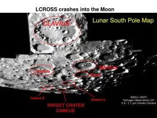
Impact Site - Baseline The mission baseline is to impact Shackleton Crater Shackleton meets the primary criteria for targeting: • Shadowed • Large (D>10 km) • Apparent association with increased [H] • High latitude (Impact Angle >70°) • Near side with portion of interior visible to Earth LP Neutron Counts (Mauriceet al.) Blue indicates [H] Shackleton Radar Topography (Margot et al.)
Impact Site Selection - Adjustments Shackleton may not be the best target given secondary considerations, including: • Visibility to Earth assets (lat and lon) and Lunar phase (position of terminator) • Site surface properties, including regolith depth (age) and surface roughness (effects the total ejecta dynamics and volume) A Target Selection Committee will consider all candidates and weigh their merit against: • Project constraints (e.g. targeting accuracy) • Project impact (due to departure from baseline) • Primary and secondary considerations.
Impact Site Selection - Process Project Impact Workshop Input Project (Baseline) ESMD / LPRP Targeting Committee “Top Five” Other Input Project (Final)
Backup Slides Backup Sides
The CBEIM and Centaur Separation Time CBEIM Ejecta Curtain Geometry • EDUS Separation Selection • To maximize S-S/C instrument response, instrument FOV should be filled at peak sunlit ejecta opacity • Sunlit ejecta opacity: • Maximum sunlit ejecta mass (assuming a 2 km sun-mask) occurs at ~1 min after impact • At 1 min after EDUS impact the ejecta curtain radius, R, is R~5 km, and at 2 min, R~15 km • To maximize the total integrated signal-to-background ratio over the maximum extent of time, the S-S/C should follow the impact by 8-10 minutes.