Download
1 / 13
130 likes | 162 Views
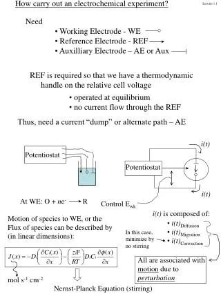
Electrode compensation of single-electrode recordings. Emulation of double-electrode recordings with a single electrode. Romain Brette UNIC. Single-electrode recordings. what we record:. (I = injected current). Bridge compensation. Estimate Ue ≈ Re I Remove Ue from the recording

E N D
Electrode compensation of single-electrode recordings Emulation of double-electrode recordings with a single electrode Romain Brette UNIC
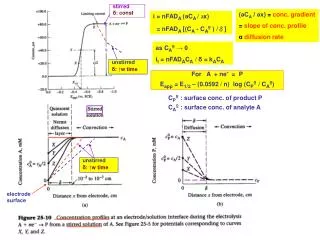
Single-electrode recordings what we record: (I = injected current)
Bridge compensation • Estimate Ue ≈ Re I • Remove Ue from the recording (Re is manually adujsted)
Capacitive transients • In fact, the electrode has a non-zero charge time • Bridge compensation makes capacitive transients appear
Capacitance neutralization • Principle : add a negative capacitance (analogical compensation circuit) • Reduce width, not height of the transients (down to ≈0.1 ms) • Feedback increases oscillatory noise + too much compensation leads to instability
Dynamic clamp • I(t) = g(t) (V(t)-E(t)) • capacitive transients are injected back → instability (oscillations)
Discontinuous Current Clamp (DCC) • Idea: inject and record in turn • Issues: • a lot of additional noise • low sampling rate (3 kHz) • Validity domain: e << m → inaccurate near spike initiation → inaccurate during high-conductances states
A new recording mode: full electrode compensation • electrode = arbitrary linear filter Ue = Ke * I Convolution: • a) Find Ke b) Compensate the recording: Vm = Vr – Ke * I
Finding the filter • Vr = K*I, with K = Km + Ke where Km = neuron filter Ke = electrode filter • Inject small white noise • Then K(s)=<Vr(t)I(t+s)> • Remove Km from K (Km and Ke have different time scales)
Results: pulse injection raw recording compensated recording
Results: injection of white noise current raw recording compensated recording zoom: action potential
Electrode filters 1) Feedback delay 2) Electronics filter 3) Electrode filter (timesteps = 0.1 ms) 1 2 3
Applications and perspectives • White noise injection • Accurate injection of noisy conductances • Single-electrode patch-clamp recordings • Accurate single-electrode voltage-clamp