Download
1 / 11
110 likes | 209 Views
Skylights Vertical vs. Splayed. By: Lisa Bornemann & Brad Koehler. Goals.

E N D
SkylightsVertical vs. Splayed By: Lisa Bornemann & Brad Koehler
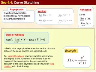
Goals For our final project, we studied the skylight system found in the University Support Building, located across Park Avenue. There are large skylights through the main corridor of the support building. We chose to study the changes in illuminance levels while varying the parameters of the skylight. In this presentation, we took actual measurements with an illuminance meter and we ran Radiance for the same situation. These numbers turned out to be quite different in magnitude, but the patterns of higher or lower illuminance values were the same. These values may differ because the dimensions of the real skylight well, the height of the glass pyramid, and the width of the mullions were eye balled. Also, while we were taking the measurements, the sky conditions were relatively clear, but there were clouds in the sky that would block the sun at times. We waited patiently to take the measurements when the sun was not being shaded by clouds and the area of the sky above the skylight was relatively clear. Still, with some puffy clouds in the sky, they may have affected the results as compared to the description of what clear sky conditions is on Radiance which is the condition we used to run our tests. Throughout the presentation we have shown our different modeled situations and the illuminance measurements obtained through running Radiance. We will compare these measurements and explain how the different parameters change the output data. The actual skylight has a 10 foot well with a 9 ft. by 9ft. opening. The glass is in a 3 ft. high pyramid shape with 4 in. mullions. We have chosen to discuss four modified situations: a 5 foot well, no well, a 5 foot splayed and 5 foot vertical well, and a 5 foot splayed with no vertical well. For a corridor, only 5 footcandles is required according to the IES handbook. The average illuminance with the current skylight is about 250 footcandles. So obviously the requirement is met. In this presentation, we are not going to determine which skylight is the best, but we are going to explain how the illuminance levels change with the different situations. This information can then be used to determine which skylight will be the best design for particular situations requiring different illuminance levels.
Information Used • The transmittance of the glazing was calculated by taking the illuminance outside and the luminance inside aimed at the skylight glass. Lemitted= 805 cd/m2 Eincident = 4900 lux Transmittance = Π*Lemitted / Eincident = 0.52 *Note: Transmittance used in Radiance is 0.534 • Sky conditions for all situations were considered clear. • The date the measurements were made and calculations were ran for April 18th. • All actual measurements were made between 2pm and 3pm, so in Radiance, the time used was 2:30 pm. • All illuminance measurements shown throughout the presentation are in footcandles. • Throughout the presentation, four corner points will be discussed. Corner 1 through 4 in the counter clockwise direction. The color key below will help make them easier to reference: corner 1 corner 2 corner 3 corner 4
Original Design ~ 10 ft. Well Actual illuminance levels obtained by taking measurements with an illuminance meter at the site:
5 ft. Well In this model, the illuminance striking the floor was higher than the illuminance on the floor of the 10 ft. well design. We feel that because this well is smaller than the previous, there are fewer bounces of reflected light. The result is a higher illuminance level across the floor because less light is absorbed by the well walls. Also, you will notice that corner 2 has the highest illuminance of all of the corners while in the 10ft. well, the diagonal corner (corner 4) has the highest illuminance. We feel this occurs because in the shorter well, more light directly hits the floor opposite the sun. Corner 2 is getting directly hit by the sun’s rays.
No Well In this model, the illuminance striking the floor was higher than the illuminance on the floor of the 5 ft. well design. We feel again that because there is no well, there is no reflected light. The result is a higher illuminance level across the floor because no light is absorbed by the well walls. The pattern formed on the illuminance grid is the same as the 5ft with the highest illuminance in corner 2.
Splayed w/ 5 ft. Well In this model, the illuminance striking the floor was higher than the illuminance on the floor of both the 5ft and 10ft wells. The splayed parts of the well will reflect light downward with less bounces. Also, a splayed well yields a larger source of light. We feel these are both reasons that the illuminance is higher. The pattern formed on the illuminance grid is the same as the 5ft and no well with the highest illuminance in corner 2.
Splayed w/out Well In this model, the illuminance striking the floor was higher than the illuminance on the floor of the splayed with a 5ft well. Less bounces occur because there is no vertical well. Also, a splayed well yields a larger source of light. We feel these are both reasons that the illuminance is higher. The pattern formed on the illuminance grid is the same as that of the splayed with a 5 ft well with the highest illuminance in corner 2.
Conclusion • A shorter vertical well will yield a higher illuminance level on the floor due to less light being absorbed by the well walls. • A splayed well will yield higher illuminance levels than a vertical well of similar proportional. • A splayed well becomes a larger light source and will therefore spread more light over a larger area, thus increasing the illuminance directly below the well.