Download

1 / 43
430 likes | 660 Views
Active Ankle-Foot Orthotic. Team P13001 Nathan Couper, ME Bob Day, ME Patrick Renahan, IE Patrick Streeter, ME. Air Muscle Tethered.

E N D
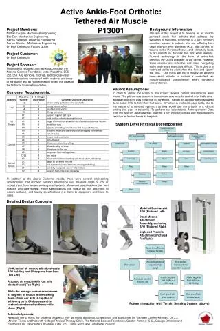
Active Ankle-Foot Orthotic Team P13001 Nathan Couper, ME Bob Day, ME Patrick Renahan, IE Patrick Streeter, ME Air Muscle Tethered This material is based upon work supported by the National Science Foundation under Award No. BES-0527358. Any opinions, findings, and conclusions or recommendations expressed in this material are those of the author and do not necessarily reflect the views of the National Science Foundation.
Agenda • Assumptions • Customer Needs • Engineering Specifications • Test Plan • Mechanical Analysis • Proximal Attachment • Static Analysis • Fatigue Analysis • Distal Attachment • Static Analysis • Fatigue Analysis • Air Muscle Testing • Transient Flow • Muscle Contractions • Risk Assessment • Proposed Schedule • Questions and Criticism
Assumptions and Project Scope • Patient maintains zero muscle control over dorsi-flexion, plantar-flexion, and toe extension • This product is designed to be used on a treadmill in a clinical setting; but can be incorporated into an aquatic setting • Tethered System • The elastomer can be adjusted on a patient basis so that when the patient’s full weight is applied on the AFO, the foot rests at angle slightly above 90 degrees with respect to the patient’s lower limb • Designed patient has the ability to use a dorsi-flex assist AFO without receiving tone-lock spasms • For calculations: • Anthropometric Data is from the ANSUR (military) Database • Based on the 50th percentile man • 2D system • no resistive forces/friction associated with the joints • a normal gait cycle time of 1.2 to 1.5 steps per second is assumed • Isotropic, Elastic Materials
Engineering Specs *Nominal value represents the initial target value for specifications. **Ideal value represents the adjusted target value for specifications based on research and adjusted objectives.
Gait Analysis Based on 88 cycles per minute: 0.30 seconds from foot off to foot strike.
Assumed AFO Design • Designs based around AFO of this structure • Design is flexible so it will be able to work on many different AFO designs and shapes • Assumed material =
Proximal Muscle Attachment • Relatively simple components • Low Profile • Strong • Removable • Key Components: • Weld Nut • Exterior threading for nut • Secures device to AFO • Screw clamps air inlet and muscle attachment to weld nut • Nozzle screws into block
Weld Nut • Uses 5/16” Nut to secure against AFO • Note external threads not shown • 316 Stainless Steel • Allows for easy removal of device • Stress Calculations: • Treated like a cantilever beam • 130 N force (Max force air muscle can apply) • Max Bending Stress: 57.45 Mpa • Shear Stress: 7.49 MPa
Proximal Anchor and Air Inlet • Houses weld nut and exterior nut • Applies force on weld nut • Also clamped on by ¼-20 screw • 1/4-inch air inlet channel • Threaded hole for nozzle insertion • 316 Stainless Steel
Proximal Anchor and Air Inlet Element Type: Solid 10node187 (tetrahedral) Max Stress: 45 MPa
Proximal Anchor and Air Inlet All displacement is about 0 meters
Nozzle • Proposed Materials: Delrin or Stainless Steel • Threading • External Threading not pictured • Screws into Proximal Anchor to allow air supply to muscle • Air muscle clamps on to cylinder • Max Stress: 2.85 Mpa • Yield Stress: • 63 MPa (Delrin) • 290 Mpa (316)
Fatigue Analysis • Fatigue Results: (Using an applied force of 53 N rather than 130N) • Weld Nut • FOS=15.53 • Proximal Anchor • FOS=20.46 • Nozzle (316 Stainless Steel) • FOS=316.9 • Nozzle (Delrin) • FOS=37.6 • 316 Stainless Steel Properties: • Endurance Limit (Se): 270 MPa • Ultimate Strength (Sut): 579 MPa • Delrin Properties: • Endurance Limit (Se): 32 MPa • Ultimate Strength (Sut): 69 MPa
Tendon Cable Use 1.5 mm diameter cable Will use bicycle brake cable Braided Stainless Steel cable Tension can be easily adjusted Preliminary calculations make us believe this solution will be more durable than previous air muscle tendon materials Maximum stress = 100.2 MPa; yield stress = 290 Mpa Factor of Safety = 11.5 Maximum Deformation = 0.233 mm
Distal Muscle Plug • Presses against Distal Muscle Plug Plate with slot for tendon cable to rest in • Plugs distal end of air muscle • No air nozzle needed at the distal end • Proposed Material = Delrin
Maximum Stress = 8.5 MPa Yield Stress = 63 MPa
Distal Muscle Plug Plate • Presses against Distal Muscle Plug • Creates friction on tendon cable, • Allows for tension in tendon cable to be easily adjusted • Proposed Material = 316 Stainless Steel • Necessary Screw Clamping Force = 0.358 N-m
Heel Cable Attachment Point • Attaches distal end of tendon cable to AFO heel protrusion • Held in place by 10-24 screw at distal end, Heel Cable Attachment Pin at proximal end • Allows for: • full range of motion of tendon cable • ease of cable changeover • Proposed Material = 316 Stainless Steel
Fatigue Analysis • Analyzed with stresses from 53 N force as opposed to 130 N • This will be more realistic to values seen during normal operation • Ultimate Strength = 579 MPa • Endurance Strength = 270 MPa • Factor of Safety = 36.8
Heel Cable Attachment Pin Proposed Material = 316 Stainless Steel
Air Muscle Construction • Outer Sleeve • Inner Tube • Clamp • End
Muscle Testing • Goal of .1 sec inflation time, max of .2 sec, estimated via gait analysis • Function of pressure and flow rate • 4.45cm contraction required for full range of motion • Function of muscle construction
Transient testing • Started by calculating the theoretical flow • Realized this is questionably accurate and very complex • Decided it would be easier and more accurate to directly measure inflation time • Took video of the muscle inflating and counted the number of frames it took to move.
Transient testing • 5 video tests
Muscle Contraction • The muscle was loaded with 53N and inflated
Input from Terrain Sensing System Flat terrain Ascending terrain (up stairs/up ramp) Descending terrain (down stairs/down ramp) Relax air muscle Release air Ankle angle at foot strike = -14.65 deg Ankle angle at foot strike = -44.96 deg Gait speed info from sensors Gait speed info from sensors. Programming Flow Chart
Test Plan https://edge.rit.edu/edge/P13001/public/WorkingDocuments/Project%20Management See Edge:
Schedule for MSD II • Reference EDGE website for working, detailed project schedule: • Planning and Execution – Project Plans and Schedules – “Schedule of Action Items” • http://edge.rit.edu/edge/P13001/public/Planning%20%26%20Execution