Download
1 / 36
370 likes | 526 Views
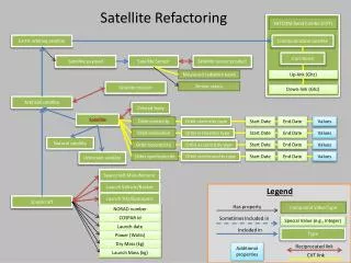
SDLS (Satellite Data Link System) SYSTEM PRESENTATION. ICAO ACP Working Group C - Toulouse October 2003 ACP WGC6/WP1 9. PRESENTATION PLAN. PART I - INTRODUCTION & CONTEXT PART II - SDLS SYSTEM DESIGN PRESENTATION PART III - PROJECT STATUS AND WAY FORWARD. PART I - INTRODUCTION & CONTEXT.

E N D
SDLS (Satellite Data Link System) SYSTEM PRESENTATION ICAO ACP Working Group C - Toulouse October 2003 ACP WGC6/WP19
PRESENTATION PLAN • PART I - INTRODUCTION & CONTEXT • PART II - SDLS SYSTEM DESIGN PRESENTATION • PART III - PROJECT STATUS AND WAY FORWARD
SDLS a CANDIDATE to NEXSAT INITIATIVE The European Space Agencyand Eurocontrol areco-ordinating their effort • An Agreement of Co-operation has been signed and one task is to progress the definition of a Next Generation Satellite System
SDLS AND NEXSAT CONTRIBUTIONS • Eurocontrol and ESA associate their effort to develop a New Generation Aeronautical Satellite System
SDLS MISSIONS • SDLS Definition • SDLS is as a potential Next Generation Aeronautical Communication System • SDLS Missions • as specified in Eurocontrol Mission Requirement Document, in line with Nexsat initiative • Complement the VHF communication system in Europe • Support datalink applications deployment in dense Airspace • World-wide coverage / Regional deployment capabilities • Supports communications needs on remote and oceanic airspace • Interoperable / Open architecture
SDLS GENERAL CONCEPT • Safety dedicated system (ATS and AOC communication) • Operation in protected radio-spectrum band ( L-band AMS(R)S ) • Network security through clearly segregated system • Controlled network with Guaranteed Performances • Low cost infrastructure and operational cost • Light and easy to install terminal • Omnidirectional antenna • Mono-Transmission Channel terminal • Based on up-to-date communication technology • Compatible to proven Bent-pipe Geostationary satellites • Distributed network implementation capability (reduced ground network infrastructure) • Capability for low cost GES implementation (in Ku band) • Optimised network architecture (Spectrum efficiency)
SDLS SERVICES • Services supported : • ATM services (Services link2000+) • AOC services (including support of ACARS) • Critical Short data services • Voice services (Point to Point, Party Line)
QUALITY OF SERVICE DATA SERVICES VOICE SERVICES
SDLS HIGH LEVEL SPECIFICATIONS • Basic raw data rate 5.6kbps over dense areas (regional spot beams) • Reduced raw data rate 3.2kbps over oceanic and remote airspace (global beams) • BER : 10-5 for data, 10-3 for voice - Link availability 99.99 % • QoS management
SDLS DESIGN PARADIGMS • Direct Sequence Code Division Multiple Access System (DS-CDMA) • + • Geostationary bent-pipe satellites • Advantages of this configuration : • Cancellation of Near-Far limitation of terrestrial CDMA systems • Cancellation of frequency guard bands due to AES Doppler • Cancellation of time guard with TDMA/CDMA configuration • Resistance to interference, multipath and fading (scintillation..) • Other by-products of interest : • Supports decentralised access scheme • Security at radio transmission level
WAVEFORM (Results of optimisation studies) • CDMA Access mode • Similar waveform on forward and return links • Synchronous/Quasi Synchronous CDMA scheme • alignment spec.1/8 of a chip • Reference carriers for synchronisation and power control • Asynchronous transmissions limited to GES and AES network entries • Modulation QPSK with pulse shaping • Spreading : Gold codes with a spread factor of 127 (BW=1MHz) • Single Data/Voice Channel Coding : • Turbo code with rate 1/2 • Eb/No=2.6dB (256 bits blocks)
BASIC AES CHARACTERISTICS • Design target : low cost SATCOM terminal • (i.e. similar to a VHF radio). • Basic Terminal • Mono-transmit channel terminal with 30W HPA operated at saturation • Omnidirectional antenna (0dBi at 5°, G/T -25dB/K) • Include all the protocol stacks • Supports Arinc 429 or Arinc 664 Interfaces • Terminal Option • AERO-I/H existing terminals supported (better EIRP-G/T figures) • Up to 22kbps (4 times basic rate) could be provided
A Generic Distribution T CHANNEL T T T T ... T T CDMA Codes n AES1 8 AES2 AES3 2 AES4 1 C C A A A Generic Distribution A CHANNEL A T T T Ar Ad Ar Ad ... Ar Ad Dedicated Return Carriers shared by several AES (Except voice multiplexed carriers) T AES1 AES2 AES3 AES4 Collision AES1 and AES3 ACCESS - CARRIER DISTRIBUTION Common ASYNC CDMA shared by all AES (Spread-ALOHA). Log-on purpose (L channel) AES Forward CDMA carriers AESx P and C AES2 AES3 GES AES1 AES4
ACCESS - CARRIER DEFINITION • Typical payloads / bursts • P, T, C : 150 bytes (Long Block Data Unit) • A :Ar : 32 bytes (Short Block Data Unit) • Ad : 8 bytes (Super Short Block Data Unit)
Optimised Satellite Gateway Network Architecture Paradigm
Gateway vs. Transparent Example • Protocol Overhead reduction • Minimal retransmissions • Channel efficiency optimisation • Flow control Satellite Link Optimised Interface SDLS Gateway Model Network Dependent Interface Transparent Network Model
Supported Diversity Schemes • SDLS Design can be instantiated with diversity schemes at several levels : • AES : • Two patch antenna to avoid masking • 2Rx / 1 Tx terminal • 2Rx / 2 Tx terminals • GES : • GES site diversity in Ku band the feeder links to remove rain attenuation effect (up to 10dB) • Satellite : • Two satellites in hot redundancy
System Expandability • SDLS is fully scalable. • Minimal Configuration • Operation in a single spot with one control and traffic station NMS/GES • Multi GES • Many GES can be instantiated in the system • Transparent introduction allowed by the CDMA structure of the system • Multi Frequency Slots • Expandability by steps of 500/1000KHz on the same transponder • Multi Spots • On the same satellite, several spots can be used simultaneously • Only one Network Master Station required for all spots • Multi Satellite • All system expansions are transparent to the Avionics
PERFORMANCE FIGURES (I) • SDLS Traffic and capacity assumptions (from Eurocontrol ref.) • Capacity assessment per aircraft
<27 s <7,2 s Priority 2 (QoS3) Priority 3 (QoS4 & 5) FDW RT Transit Delay (sec) P P Long* Short Ar Short P T Long* 12,29 T P P T Priority 1 (QoS1 & 2) 4,41 <4,5 s 3,30 6,71 7,65 Ar PERFORMANCE FIGURES (II) • Initial Simulation Results • Hypothesis & Modelling • Queuing Analysis based on Markov models • One GES configuration / One spot beam • PIAC of 2000 aircrafts • Preliminary Results *Long packets imply to make a reservation on A channel
Forward P channels 27 30 Number of CDMA channels Return A channel TBD TBD 1 GES configuration 15 GES configuration* Return T channel 13 15 Totalnumber TBD TBD *Uniform PIAC AES distribution among 15 GES PERFORMANCES (III) • Summary Table: Total number of CDMA channels (PIAC 2000 aircrafts)
COST FIGURES (I) • SDLS Service Unit Costs: Results for Data Cost Hypothesis : Space capacity lease from 1 to 2M€/year/MHz/39dBW
COST FIGURES (II) • SDLS Service Unit Costs: Results for voice Cost Hypothesis : Space capacity lease from 1 to 2M€/year/MHz/39dBW
EXPERIMENTATION STATUS • Slide 1 : Initial Feasibility study • Slice 2 : SDLS Demonstrator Baseline system qualified in July 2002, with : • SDLS Network elements : NMS - GES - 2 AES • SDLS Test Bed : set ATS and AOC applications • SDLS Demonstrator Extension under completion : • System Qualified on ESA Artemis Satellite (September 2003) • Second Access Station deployed in Rome (November 2003) • Slice 3 : SDLS Operational system study On-going • SDLS Experimentation Plan for next phase include : • Performance test bench development (transmission and network simulations) • Real life test based on SDLS Demonstrator (with embarked tests)
SDLS SLICE 3 - WBS Service Analysis Economic Analysis Experimentation Detailed Studies System Consolidation
SDLS SLICE 3 : STUDY PHILOSOPHY Making top-down and bottom-up approaches converge User needs Analysis, Service Requirements Future SATCOM Solution SDLS feasibility analysis and technical solutions Solutions & Trade-Offs Access Protocols Waveform
SDLS SLICE 3 STUDY OVERVIEW Thales ATM (F) Indra (SP) AlcatelSpace Schlumberger Sema (SP) Airtel (Ir) Alcatel Bell (B) Vitrociset (I) Skysoft (P)
Slice 3 : Operational System Study Status • Core studies have been conducted • Services and QoS figures defined • Baseline system architecture defined • Studies currently on-going with short term results expected • Transmission : • Alternative spreading/scrambling schemes performance evaluation • Envelope variation minimisation through complex scrambling • Code reuse between spot using scrambling • TCM-8PSK evaluation (bandwidth reduction) • Reduced spreading option analysis in 500kHz bandwidth • Network Architecture : • Access performance refinement • Gateway stack definition and performance refinement • System consolidation activity on-going • Outputs : • System Design Concepts Justification File • System Functional Specification
OPEN ISSUES & WAY FORWARD • Consolidation of Mission Requirements with Eurocontrol • Performances Verification • Simulation models to be developed to confirm preliminary results • network/protocol efficiency, capacity, QoS compliance • system availability refinement (scintillation effects…) • Safety assessment • Safety analysis to be performed • Security requirements • Functions linked to security management could be included in the design if required (authentication / crypto / ..) • Experimentation • Leverage existing system demonstrator to validate system key features (access diversity, gateway prototyping, environmental tests including in-flight demonstrations)
SDLS 2004 - 2005 SDLS Demonstrator System Prototype Experimentation EXPERIMENTATION Flight Test Pre-Operation SDLS Slice 3 Pre-Operational System SDLS Phase B Completion System Specification DEVELOPPEMENT D SDLS Phase C MRD V1 • CDR MRD V2 • PDR SARPS/MOPS NexSat Initiative STANDARDISATION Users Steering Group Contribution to ICAO 2005 2003 2004