Download
1 / 9
100 likes | 273 Views
Electron Beam I nduced C hemistry. Collected from many articles in the subject. This articles are listed in the appendix A. Special thank you to Anthony Garetto , who collected all of them in one folder for me. Dr. V. Recommends.

E N D
Electron Beam Induced Chemistry Collected from many articles in the subject. This articles are listed in the appendix A. Special thank you to Anthony Garetto, who collected all of them in one folder for me. Dr. V. Recommends
The deposition rate R: molecules per unit area per unit time, at the incident point directly depends on f(E_0) flux of electrons passing through the surface. Which means higher energy will make more electrons pass through the same unit area per sec. σ(E_0) interaction cross section, which depends on E_0, and it is not directly proportional N molecular density on the surface. My thoughts: Because of f and σ there is an optimum electron energy level that provides the highest possible deposition rate R. Less energy than that optimal one would mean less f, on the other hand more energy than would reduce σ. MeRiT Educational
An important parameter needed for the prediction of the deposited geometry is the electron-impact dissociation cross section σ. This parameter, specific for each type of precursor molecule, in practice is only known for a few gases. σ_max, the maximum cross section, can be calculated as a function of the number of carbon #C and hydrogen #H atoms present in the molecule, as follows: σ_max = (1.89#C + 0.33#H – 0.505)x10^(-2) [nm^2] E_max, the energy at which the maximum cross section occurs, and λ, a constant that determines the rate of decay of the cross section E_max. E_th is the threshold energy for molecular dissociation and is always around 10 eV for gas-phase hydrocarbons. When the gas molecule is adsorbed on a surface, the dissociation threshold energy is shifted to values lower than that in the gas. C2H5 dissociation cross section for the adsorbed phase shows E_th=3.5 eV with a E_max of 18 eV and λ of 77 eV. MeRiT Educational
The analysis of the spatial resolution has been reduced to the prediction of the shape of the structures deposited under electron-beam irradiation. The smaller the beam diameter, the more important is the role played by SEs. The ultimate EBID resolution, calculated for a zero-diameter electron beam and a very thin target (10nm), according to our model is around 0.23nm. However, the SEs scattered in the freshly grown structure are imposing a larger limit on the spatial resolution of EBID. This is the feasible EBID resolution of 2nm as soon as the height of the structure exceeds a few monolayers. MeRiT Educational
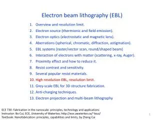
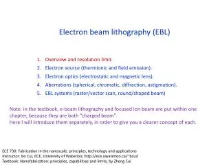
As high-energy electrons were considered not suitable for EBID due to their broad distribution of secondary electron energies and small cross sections for decomposition reactions, most of the previous EBIDs were performed in conventional scanning electron microscopes (SEMs) using low-energy electrons in the range of 1 – 30 keV. The growth rate of the upside part is much lower for 200keV electrons. As the incident beam energy is increased, the yields of backscattered electrons and secondary electrons that contribute to EBID drip quickly. Thus the productive efficiency of the high-energy electrons is lower. The ratio between adsorbed precursor flux and charged particle flux at the deposition/etch area crucially determine the deposition and etch rate. MeRiT Educational
A combination of electromagnetic and electrostatic final lens leads to ultrahigh resolution at low voltages, around 3nm spot size at 1 keV electron energy. Low voltage operation has proven indispensable to avoid unintended artifacts: for exampl, halos during deposition. River-bedding usually occurs in focused-ion-beam processing, because the edge of a layer is removed faster than the inside of the layer due to the increase of removal rate as a function of the angle of incidence. This increase results in the formation of a trench into the substrate around the edge of the removed layer. The cross-sections for C-H bond rupture at the terminal methyl groups have onsets with incident energies E_i ~ 7 eV and well-resolved maxima at 10 eV. MeRiT Educational
Acceleration voltage: Experiments show the increase of deposition rate at lower beam energies. The interaction cross section of adsorbed precursor molecules increases with decreasing energy of primary electrons. A correlation with the secondary electron yield was found. This is interpreted as indication that secondary electrons contribute significantly to an increased deposition rate at low acceleration voltage. Dwell time: If readsorption is faster than consumption, the deposition rate would be constant at all dwell times. The experimental results show that the deposition rate increases linear with decreasing dwell time. Hence, even for a single pixel within the scan pattern the deposition rate is adsorption limited. MeRiT Educational
The overall area where precursor molecules impinge is often millimeter size and little is known about the precursor density at the nanometer sized deposition/etch spot. The precursor density determines whether the process is electron or precursor limited. MeRiT Educational
“Spatial resolution limits in electron-beam-induced deposition”, N. Silvis-Cividjian, C.W. Hagen, P.Kruit, Delft University of Technology, Faculty of Applied Science, Lorentzweg 1, 2628 CJ Delft, The Netherlands, 24 October 2005, Journal of Applied Physics 98, 084905 “Limits of 3-D nanostructures fabricated by focused electron beam (FEB) induced deposition”, P.Hoffmann, I.Utke, F.Cicoira, Institure of Imaging and Applied Optics, School of Engineering (STI), EcolePolytechnique de Lausanne, CH-1015 Lausanne-EPFL, Switzerland, June 2002 “The use of electron beam exposure and chemically enhanced vapor etching of SiO2 for nanoscale fabrication”, M.N. Kozicki, J. Allgair, A. Jenkins-Gray, D.K. Ferry, T.K. Whidden, Center for Solid State Electronics Research, Arizona State University, Tempe, AZ 85287-6206, USA, Physics B 227 (1996) 318-322 “Modeling the Process of Electron-Beam-Induced Deposition by Dynamic Monte Carlo Simulation”, Zhi-Quan LIU, Kazutaka MITSUISHI, Kazuo FURUYA, Japanese Journal of Applied Physics, Vol. 44, No. 7B, 2005, pp.5659-5663 “Testing new chemistries for mask repair with focused ion beam gas assisted etching”, Andrei Stanishevsky, Klaus Edinger, Jon Orloff, John Melngailis, Institute for Research in Engineering and Applied Physics, University of Maryland, College Park, Maryland 20742, Diane Stewart, FEI Corporation, 1 Corporation way, Peabody, Massachusetts 01960, Alvina Williams, Richard Clark, International SEMATECH, Austin, Texas 78741, 10 December 2003 “Electron-beam-based photomask repair”, Klaus Edinger, Hans Becht, Johannes Bihr, Volker Boegli, Michael Budach, Thorsten Hofmann, Hans W.P. Koops, Peter Kuschnerus, Jens Oster, Petra Spies, Bernd Weyrauch, NaWoTec GmbH, 64380 Rossdorf, Germany, 10 December 2004, American Vacuum Society “Multibeam electron source for nanofabrication using electron beam induced deposition”, M.J. van Bruggen, B. van Someren, P. Kruit, Delft University of Technology, Delft, 2628 CJ. The Netherlands, www.sciencedirect.com, Microelectronic Engineering 83 (2006) 771-775 “Electron Beam Induced Selective etching and Deposition Technology”, Shinji Matsui, ToshinoriIchihashi, Masakazu Baba, Akinobu Satoh, NEC Corporation, 34, Miyukigaoka, Tsukuba, Ibaraki, Japan, Superlattices and Microstructures, Vol. 7, No. 4, 1990 MeRiT Educational – Appendix A