Download
1 / 29
320 likes | 610 Views
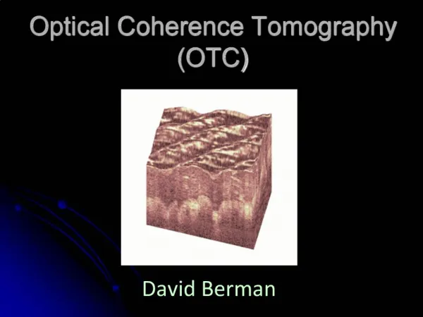
Speckle Noise Reduction in Optical Coherence Tomography. By: Marisse Foronda Rishi Matani Hardik Mehta Arthur Ortega. Cow Retina. tissue modulated wave fronts. multiple forward scatter. wave fronts. multiple back scatter. sample volume. Speckle. Background.

E N D
Speckle Noise Reduction in Optical Coherence Tomography By: Marisse Foronda Rishi Matani Hardik Mehta Arthur Ortega
tissue modulated wave fronts multiple forward scatter wave fronts multiple back scatter sample volume Speckle
Background • Minimally-Invasive to Non-Invasive imaging system • Clinically used • High Resolution alternate to ultrasound imaging • One significant problem is speckle formation
Intensity Loss • Varying Patterns can cause loss of intensity of image and change in percent reflectivity • First, we must characterize default intensity loss by placing a flat mirror at the sample arm and having no deformations on the deformable mirror • Then, we deform mirror and characterize loss: • 3 dB loss 50% loss • 6 dB loss 75% loss • 9 dB loss 87.5% loss
Pattern 1 100% 80% % light reflected Amplitude Pattern 2 100% 80% % light reflected Amplitude Image Assembly
Correlation • If two images have speckle patterns that are the same, averaging them gives us no reduction in that speckle • We have to characterize how similar two images are using the formula:
0 µW fiber and collimator deformable mirror 2D-galvo scanners 480 mW 526 mW fiber and collimator 2.5 mW 3.0 mW
1 µW fiber and collimator deformable mirror 2D-galvo scanners 480 mW 526 mW fiber and collimator 2.5 mW 3.0 mW
5 µW fiber and collimator deformable mirror 2D-galvo scanners 480 mW 526 mW fiber and collimator 2.5 mW 3.0 mW
10 µW fiber and collimator deformable mirror 2D-galvo scanners 480 mW 526 mW fiber and collimator 2.5 mW 3.0 mW
20 µW fiber and collimator deformable mirror 2D-galvo scanners 480 mW 526 mW fiber and collimator 2.5 mW 3.0 mW
35 µW fiber and collimator deformable mirror 2D-galvo scanners 480 mW 526 mW fiber and collimator 2.5 mW 3.0 mW
50 µW fiber and collimator deformable mirror 2D-galvo scanners 480 mW 526 mW fiber and collimator 2.5 mW 3.0 mW
80 µW fiber and collimator deformable mirror 2D-galvo scanners 480 mW 526 mW fiber and collimator 2.5 mW 3.0 mW
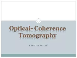
125 µW fiber and collimator output deformable mirror C2 2D-galvo scanners 480 mW G M 526 mW fiber and collimator 2.5 mW C1 input 3.0 mW
3.0 mW fiber and collimator deformable mirror 2D-galvo scanners 2.2 mW 2.1 mW 486 mW fiber and collimator 10 µW
3.0 mW fiber and collimator deformable mirror 2D-galvo scanners 2.2 mW 2.1 mW fiber and collimator 486 mW 30 µW
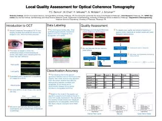
3.0 mW fiber and collimator Input deformable mirror C1 2D-galvo scanners 2.2 mW G M 2.1 mW fiber and collimator 486 mW C2 Output 119 µW
Power Results Forward Alignment Reverse Alignment -AR (anti-reflection) coating on Galvo mirrors (1310 nm) -Fibers (1310 nm) -Power Source (800 nm)
Conclusion • Quantitative Benchmark: Reduce contrast ratio by 25% - 50% with a 6 dB mean intensity loss • Future Applications: Any Imaging system using a coherent light source can easily integrate the deformable mirror component. • Integration of the mirror will be efficient and cost effective.