Download
1 / 28
280 likes | 382 Views
FIRE Advanced Tokamak Progress. C. Kessel Princeton Plasma Physics Laboratory NSO PAC 2/27-28/2003, General Atomics. 0D Operating Space PF Coils Equilibrium/Stability ECCD/Neoclassical Tearing Modes RWM Stabilization ICRF, FWCD, LHCD TSC-LSC Simulations 8. Further Work ---> PVR.

E N D
FIRE Advanced Tokamak Progress C. Kessel Princeton Plasma Physics Laboratory NSO PAC 2/27-28/2003, General Atomics 0D Operating Space PF Coils Equilibrium/Stability ECCD/Neoclassical Tearing Modes RWM Stabilization ICRF, FWCD, LHCD TSC-LSC Simulations 8. Further Work ---> PVR
ARIES-AT Provides a Long Term Target for Advanced Tokamaks FIRE-AT will need to show how close we can get to this configuration thru control in a burning plasma Steady state Strong plasma shaping Large bootstrap fraction, minimal CD High Transport that supports high fBS and high Plasma edge solution that supports CD, power handling, divertor solution
0D Operating Space Analysis for FIRE AT • Heating/CD Powers • ICRF/FW, 30 MW • LHCD, 30 MW • Using CD efficiencies • (FW)=0.20 A/W-m2 • (LH)=0.16 A/W-m2 • P(FW) and P(LH) determined at r/a=0 and r/a=0.75 • I(FW)=0.2 MA • I(LH)=Ip(1-fbs) • Scanning Bt, q95, n(0)/<n>, T(0)/<T>, n/nGr, N, fBe, fAr • Q=5 • Constraints: • (flattop)/(CR) determined by VV nuclear heat (4875 MW-s) or TF coil (20s at 10T, 50s at 6.5T) • P(LH) and P(FW) ≤ max installed powers • P(LH)+P(FW) ≤ Paux • Q(first wall) < 1.0 MW/m2 with peaking of 2.0 • P(SOL)-Pdiv(rad) < 28 MW • Qdiv(rad) < 8 MW/m2
FIRE’s Q=5 AT Operating Space Access to higher tflat/j decreases at higher N, higher Bt, and higher Q, since tflat is set by VV nuclear heating Access to higher radiated power fractions in the divertor enlarges operating space significantly
FIRE’s AT Operating Space Q = 5-10 accessible N = 2.5-4.5 accessible fbs = 50-90+ accessible tflat/tj = 1-5 accessible If we can access….. H98(y,2) = 1.2-2.0 Pdiv(rad) = 0.5-1.0 P(SOL) Zeff = 1.5-2.3 n/nGr = 0.6-1.0 n(0)/<n> = 1.5-2.0
Examples of Q=5 AT Points That Obtain flat/J > 3 HH < 1.75, satisfy all power constraints, Pdiv(rad) < 0.5 P(SOL)
PF Coils Must Sustain AT Plasmas with Low li and High Ip=4.5-5.5 MA, Bt=6.5-8.5T 100% non-inductive in flattop Ip can not be too low or we’ll loose too many alphas from ripple Inductive + non-inductive rampup ----> consumes 19-22 V-s, what is final flux state?? Flattop times = 16-50s (from Pfusion of 300-100 MW) and TF coil Low li(3) = 0.42, N=4.2 Divertor coils are driven to high currents
PF Coil Capability for AT Modes • Advanced tokamak plasmas • Range of current profiles: 0.35 < li(3) < 0.55 • Range of pressures: 2.50 < N < 5.0 • Range of flattop flux states: chosen to minimize heating and depends on flattop time (determined by Pfusion) • Ip limited to ≤ 5.5 MA • Lower li operating space led to redesign of divertor coils • PF1 and PF2 changed to 3 coils and total cross-section enlarged • Presently examining magnet stresses and heating for AT scenarios
Neo-Classical Tearing Modes at Lower Bt for FIRE AT Modes Target Bt=6.5-7 T for NTM control, to utilize 170 GHz from ITER R&D Must remain on LFS for resonance ECCD efficiency, can local e be high enough to avoid trapping boundary?? Avoid NTM’s with j profile and q>2.0 or do we need to suppress them?? Ro Ro+a Bt=6.5 T fce=182 fce=142 170 GHz Ro Ro+a Bt=7.5 T fce=210 fce=164 200 GHz Ro Ro+a Bt=8.5 T fce=238 fce=190 Can we rely on OKCD to suppress NTM’s far off-axis on LFS versus ECCD ?? (enhanced Ohkawa affect at plasma edge)
J. Decker, APS 2002,MIT OKCD allows LFS EC deposition, with similar A/W as ECCD on HFS
Comments on ECCD in FIRE • ASDEX-U shows that 3/2 island is suppressed for about 1 MW of power with IECCD/Ip = 1.6%, giving 0.013 A/W • Ip=0.8 MA and N=2.5 • DIII-D shows that 3/2 island is suppressed for about 1.2-1.8 MW with jEC/jBS = 1.2-2.0 • Ip=1.0-1.2 MA, N=2.0-2.5 • OKCD analysis of Alcator-CMOD gives about 0.0056 A/W • FIRE’s current requirement should be about 15 times higher than ASDEX-U (scaled by Ip and N2) • Need about 200 kA, which would require about 35 MW?? Early detection reduces power alot according to ITER • Do we need less current for 5/2 or 3/1, do we need to suppress them?? • Is 170 GHz really the cliff in EC technology?? MIT, short pulse results
Updating AT Equilibrium Targets Based on TSC-LSC Equilibrium TSC-LSC equilibrium Ip=4.5 MA Bt=6.5 T q(0)=3.5, qmin=2.8 N=4.2, =4.9%, p=2.3 li(1)=0.55, li(3)=0.42 p(0)/p=2.45 n(0)/n=1.4 Stable n= Stable n=1,2,3 with no wall √V/Vo
Original AT Target Equilibrium for FIRE This needs to be revisited with Ip=4.5 MA and Bt=6.5 T • q(min) = 2.1-2.2 • r/a(qmin) = 0.8 • n(0)/<n> = 1.5 • Ip = 5.5 MA • Bt = 8.5 T • No wall stabilization • bN = 2.5 • n=1 RWM stabilized • bN = 3.65 bN = 2.5, fbs < 0.55 bN = 3.65, fbs < 0.75
Stabilization of n=1 RWM is a High Priority on FIRE Feedback stabilization analysis with VALEN shows strong improvement in , taking advantage of DIII-D experience, most recent analysis indicates N(n=1) can reach 4.2 What is impact of n=2??
FIRE Uses ICRF Ion Heating for Its Reference and AT Discharges • ICRF ion heating • 80-120 MHz • 2 strap antennas • 4 ports (2 additional reserved) • 20 MW installed (10 MW additional reserved) • He3 minority and 2T heating • Frequency range allows heating at a/2 on HFS and LFS (C-Mod ITB) • Full wave analysis • SPRUCE in TRANSP • Using n(He3)/ne = 2% • n20(0) = 5.3, <n20> = 4.4 • PICRF = 11.5 MW, = 100 MHz • THe3(0) = 10.2 keV • Pabs(He3) = 60% • Pabs(T) = 10% • Pabs(D) = 2% • Pabs(elec) = 26% Antenna design --->D. Swain, ORNL
ICRF/FW Viable for FIRE On-Axis CD Calculations assume same ICRF ion heating system frequency range, approximately 40% of power absorbed on ions, can provide required AT on-axis current of 0.3-0.4 MA with 20 MW (2 strap antennas) PICES (ORNL) and CURRAY(UCSD) analysis f = 110-115 MHz n|| = 2.0 n(0) = 5x10^20 /m3 T(0) = 14 keV 40% power in good part of spectrum (2 strap) ----> 0.02-0.03 A/W CD efficiency with 4 strap antennas is 50% higher Operating at lower frequency to avoid ion resonances, vph/vth?? E. Jaeger, ORNL
Benchmarks for LHCD Between LSC and ACCOME (Bonoli) Trapped electron effects reduce CD efficiency Reverse power/current reduces forward CD Recent modeling with CQL and ACCOME/LH19 will improve CD efficiency, but right now…….. Bt=8.5T ----> 0.25 A/W-m2 Bt=6.5T ----> 0.16 A/W-m2 FIRE has increased the LH power from 20 to 30 MW
HFS Pellet Launch and Density Peaking ---> Needs Strong Pumping Simulation by W. Houlberg, ORNL, WHIST FIRE reference discharge with uniform pellet deposition, achieves n(0)/<n> ≈ 1.25 P. T. Lang, J. Nuc. Mater., 2001, on ASDEX and JET L. R. Baylor, Phys. Plasmas, 2000, on DIII-D
HFS Launch V=125 m/s, set by ORNL pellet tube geometry Vertical and LFS launch access higher velocities
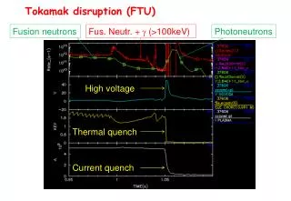
TF Ripple and Alpha Particle Losses TF ripple very low in FIRE (max) = 0.3% (outboard midplane) Alpha particle collisionless + collisional losses = 0.3% for reference ELMy H-mode For AT plasmas alpha losses range from 2-8% depending on Ip and Bt ----> are Fe inserts required for AT operation??? Optimize for Bt=6.5T
Fe Shims for Ripple Reduction in FIRE TF Coil Fe Shims Outer VV Inner VV
TSC-LSC Simulation of Burning AT Plasma in FIRE • Bt=6.5 T, Ip=4.5 MA • q(0) =4.0, q(min) = 2.75, q(95) = 4.0, li = 0.42 • b = 4.7 %, bN = 4.1,bp = 2.35 • n/nGr = 0.85, n(0)/<n> = 1.47 • n(0) = 4.4x10^20, n(line) = 3.5, n(vol) = 3.0 • Wth = 34.5 MJ • tE = 0.7 s, H98(y,2) = 1.7 • Ti(0) = 14 keV, Te(0) = 16 keV • Dy(total) = 19 V-s, • Pa = 30 MW • P(LH) = 25 MW • P(ICRF/FW) = 7 MW • Up to 20 MW ICRF used in rampup • P(rad) = 15 MW • Zeff = 2.3 • Q = 5 • I(bs) = 3.5 MA, I(LH) = 0.80 MA, I(FW) = 0.20 MA • t(flattop)/j=3.2
TSC-LSC Simulation of Q=5 Burning AT Plasma Ip=4.5 MA, Bt=6.5 T, N=4.1, t(flat)/j=3, I(LH)=0.80, P(LH)=25 MW fBS=0.77, Zeff=2.3,
AT Physics Capability on FIRE Control Strong plasma shaping and control Pellet injection, divertor pumping, impurity injection FWCD (electron heating) on-axis, ICRF ion heating off-axis LHCD (electron heating) off-axis ECCD (LFS, electron heating) off-axis, MHD control RWM MHD feedback control NBI ?? (need to examine for AT parameters!!) t(flattop)/t(curr diff) = 1-5 Diagnostics MHD J Profile P-profile Rotation
Ongoing Advanced Tokamak Work ---> PVR • Establish PF Coil operating limits • Revisit Equilibrium/Stability Analysis • Use recent GLF23 update in AT scenarios • LHCD efficiency updates • EC with FIRE’s parameters • Orbit calculations of lost alphas for scenario plasmas • RWM coil design in port plugs and RF ports • Determine possible impact of n=2 RWM on access to high N • Examine NBI for FIRE AT parameters