Data Representation in Computer Systems
940 likes | 1.22k Views
2. Chapter 2 Objectives. Understand the fundamentals of numerical data representation and manipulation in digital computers.Master the skill of converting between various radix systems.Understand how errors can occur in computations because of overflow and truncation.. 3. Chapter 2 Objectives. Und

Data Representation in Computer Systems
E N D
Presentation Transcript
1. Data Representation in Computer Systems Chapter 2
2. 2 Chapter 2 Objectives Understand the fundamentals of numerical data representation and manipulation in digital computers.
Master the skill of converting between various radix systems.
Understand how errors can occur in computations because of overflow and truncation.
3. 3 Chapter 2 Objectives Understand the fundamental concepts of floating-point representation.
Gain familiarity with the most popular character codes.
Understand the concepts of error detecting and correcting codes.
4. 4 2.1 Introduction A bit is the most basic unit of information in a computer.
It is a state of �on� or �off� in a digital circuit.
Sometimes these states are �high� or �low� voltage instead of �on� or �off..�
A byte is a group of eight bits.
A byte is the smallest possible addressable unit of computer storage.
The term, �addressable,� means that a particular byte can be retrieved according to its location in memory.
5. 5 2.1 Introduction A word is a contiguous group of bytes.
Words can be any number of bits or bytes.
Word sizes of 16, 32, or 64 bits are most common.
In a word-addressable system, a word is the smallest addressable unit of storage.
A group of four bits is called a nibble (or nybble).
Bytes, therefore, consist of two nibbles: a �high-order nibble,� and a �low-order� nibble.
6. 6 2.2 Positional Numbering Systems Bytes store numbers using the position of each bit to represent a power of 2.
The binary system is also called the base-2 system.
Our decimal system is the base-10 system. It uses powers of 10 for each position in a number.
Any integer quantity can be represented exactly using any base (or radix).
7. 7 2.2 Positional Numbering Systems The decimal number 947 in powers of 10 is:
The decimal number 5836.47 in powers of 10 is:
8. 8 2.2 Positional Numbering Systems The binary number 11001 in powers of 2 is:
When the radix of a number is something other than 10, the base is denoted by a subscript.
Sometimes, the subscript 10 is added for emphasis:
110012 = 2510
9. 9 2.3 Decimal to Binary Conversions Because binary numbers are the basis for all data representation in digital computer systems, it is important that you become proficient with this radix system.
Your knowledge of the binary numbering system will enable you to understand the operation of all computer components as well as the design of instruction set architectures.
10. 10 2.3 Decimal to Binary Conversions In an earlier slide, we said that every integer value can be represented exactly using any radix system.
You can use either of two methods for radix conversion: the subtraction method and the division remainder method.
The subtraction method is more intuitive, but cumbersome. It does, however reinforce the ideas behind radix mathematics.
11. 11 Suppose we want to convert the decimal number 190 to base 3.
We know that 3 5 = 243 so our result will be less than six digits wide. The largest power of 3 that we need is therefore 3 4 = 81, and 81 ? 2 = 162.
Write down the 2 and subtract 162 from 190, giving 28. 2.3 Decimal to Binary Conversions
12. 12 Converting 190 to base 3...
The next power of 3 is 3 3 = 27. We�ll need one of these, so we subtract 27 and write down the numeral 1 in our result.
The next power of 3, 3 2 = 9, is too large, but we have to assign a placeholder of zero and carry down the 1. 2.3 Decimal to Binary Conversions
13. 13 2.3 Decimal to Binary Conversions Converting 190 to base 3...
3 1 = 3 is again too large, so we assign a zero placeholder.
The last power of 3, 3 0 = 1, is our last choice, and it gives us a difference of zero.
Our result, reading from top to bottom is:
19010 = 210013
14. 14 2.3 Decimal to Binary Conversions Another method of converting integers from decimal to some other radix uses division.
This method is mechanical and easy.
It employs the idea that successive division by a base is equivalent to successive subtraction by powers of the base.
Let�s use the division remainder method to again convert 190 in decimal to base 3.
15. 15 Converting 190 to base 3...
First we take the number that we wish to convert and divide it by the radix in which we want to express our result.
In this case, 3 divides 190 63 times, with a remainder of 1.
Record the quotient and the remainder. 2.3 Decimal to Binary Conversions
16. 16 Converting 190 to base 3...
63 is evenly divisible by 3.
Our remainder is zero, and the quotient is 21. 2.3 Decimal to Binary Conversions
17. 17 Converting 190 to base 3...
Continue in this way until the quotient is zero.
In the final calculation, we note that 3 divides 2 zero times with a remainder of 2.
Our result, reading from bottom to top is:
19010 = 210013 2.3 Decimal to Binary Conversions
18. 18 2.3 Decimal to Binary Conversions Fractional values can be approximated in all base systems.
Unlike integer values, fractions do not necessarily have exact representations under all radices.
The quantity � is exactly representable in the binary and decimal systems, but is not in the ternary (base 3) numbering system.
19. 19 2.3 Decimal to Binary Conversions Fractional decimal values have nonzero digits to the right of the decimal point.
Fractional values of other radix systems have nonzero digits to the right of the radix point.
Numerals to the right of a radix point represent negative powers of the radix:
20. 20 2.3 Decimal to Binary Conversions As with whole-number conversions, you can use either of two methods: a subtraction method and an easy multiplication method.
The subtraction method for fractions is identical to the subtraction method for whole numbers. Instead of subtracting positive powers of the target radix, we subtract negative powers of the radix.
We always start with the largest value first, n -1, where n is our radix, and work our way along using larger negative exponents.
21. 21 The calculation to the right is an example of using the subtraction method to convert the decimal 0.8125 to binary.
Our result, reading from top to bottom is:
0.812510 = 0.11012
Of course, this method works with any base, not just binary. 2.3 Decimal to Binary Conversions
22. 22 Using the multiplication method to convert the decimal 0.8125 to binary, we multiply by the radix 2.
The first product carries into the units place. 2.3 Decimal to Binary Conversions
23. 23 Converting 0.8125 to binary . . .
Ignoring the value in the units place at each step, continue multiplying each fractional part by the radix. 2.3 Decimal to Binary Conversions
24. 24 Converting 0.8125 to binary . . .
You are finished when the product is zero, or until you have reached the desired number of binary places.
Our result, reading from top to bottom is:
0.812510 = 0.11012
This method also works with any base. Just use the target radix as the multiplier.
2.3 Decimal to Binary Conversions
25. 25 2.3 Decimal to Binary Conversions The binary numbering system is the most important radix system for digital computers.
However, it is difficult to read long strings of binary numbers-- and even a modestly-sized decimal number becomes a very long binary number.
For example: 110101000110112 = 1359510
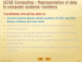
For compactness and ease of reading, binary values are usually expressed using the hexadecimal, or base-16, numbering system.
26. 26 2.3 Decimal to Binary Conversions The hexadecimal numbering system uses the numerals 0 through 9 and the letters A through F.
The decimal number 12 is C16.
The decimal number 26 is 1A16.
It is easy to convert between base 16 and base 2, because 16 = 24.
Thus, to convert from binary to hexadecimal, all we need to do is group the binary digits into groups of four.
27. 27 2.3 Decimal to Binary Conversions Using groups of hextets, the binary number 110101000110112 (= 1359510) in hexadecimal is:
Octal (base 8) values are derived from binary by using groups of three bits (8 = 23):
28. 28 2.4 Signed Integer Representation The conversions we have so far presented have involved only positive numbers.
To represent negative values, computer systems allocate the high-order bit to indicate the sign of a value.
The high-order bit is the leftmost bit in a byte. It is also called the most significant bit.
The remaining bits contain the value of the number.
29. 29 2.4 Signed Integer Representation There are three ways in which signed binary numbers may be expressed:
Signed magnitude,
One�s complement and
Two�s complement.
In an 8-bit word, signed magnitude representation places the absolute value of the number in the 7 bits to the right of the sign bit.
30. 30 2.4 Signed Integer Representation For example, in 8-bit signed magnitude, positive 3 is: 00000011
Negative 3 is: 10000011
Computers perform arithmetic operations on signed magnitude numbers in much the same way as humans carry out pencil and paper arithmetic.
Humans often ignore the signs of the operands while performing a calculation, applying the appropriate sign after the calculation is complete.
31. 31 2.4 Signed Integer Representation Binary addition is as easy as it gets. You need to know only four rules:
0 + 0 = 0 0 + 1 = 1
1 + 0 = 1 1 + 1 = 10
The simplicity of this system makes it possible for digital circuits to carry out arithmetic operations.
We will describe these circuits in Chapter 3.
32. 32 2.4 Signed Integer Representation Example:
Using signed magnitude binary arithmetic, find the sum of 75 and 46.
First, convert 75 and 46 to binary, and arrange as a sum, but separate the (positive) sign bits from the magnitude bits.
33. 33 2.4 Signed Integer Representation Example:
Using signed magnitude binary arithmetic, find the sum of 75 and 46.
Just as in decimal arithmetic, we find the sum starting with the rightmost bit and work left.
34. 34 2.4 Signed Integer Representation Example:
Using signed magnitude binary arithmetic, find the sum of 75 and 46.
In the second bit, we have a carry, so we note it above the third bit.
35. 35 2.4 Signed Integer Representation Example:
Using signed magnitude binary arithmetic, find the sum of 75 and 46.
The third and fourth bits also give us carries.
36. 36 2.4 Signed Integer Representation Example:
Using signed magnitude binary arithmetic, find the sum of 75 and 46.
Once we have worked our way through all eight bits, we are done.
37. 37 2.4 Signed Integer Representation Example:
Using signed magnitude binary arithmetic, find the sum of 107 and 46.
We see that the carry from the seventh bit overflows and is discarded, giving us the erroneous result: 107 + 46 = 25.
38. 38 2.4 Signed Integer Representation The signs in signed magnitude representation work just like the signs in pencil and paper arithmetic.
Example: Using signed magnitude binary arithmetic, find the sum of - 46 and - 25.
39. 39 2.4 Signed Integer Representation Mixed sign addition (or subtraction) is done the same way.
Example: Using signed magnitude binary arithmetic, find the sum of 46 and - 25.
40. 40 2.4 Signed Integer Representation Signed magnitude representation is easy for people to understand, but it requires complicated computer hardware.
Another disadvantage of signed magnitude is that it allows two different representations for zero: positive zero and negative zero.
For these reasons (among others) computers systems employ complement systems for numeric value representation.
41. 41 2.4 Signed Integer Representation In complement systems, negative values are represented by some difference between a number and its base.
In diminished radix complement systems, a negative value is given by the difference between the absolute value of a number and one less than its base.
In the binary system, this gives us one�s complement. It amounts to little more than flipping the bits of a binary number.
42. 42 2.4 Signed Integer Representation For example, in 8-bit one�s complement, positive 3 is: 00000011
Negative 3 is: 11111100
In one�s complement, as with signed magnitude, negative values are indicated by a 1 in the high order bit.
Complement systems are useful because they eliminate the need for subtraction. The difference of two values is found by adding the minuend to the complement of the subtrahend.
43. 43 2.4 Signed Integer Representation With one�s complement addition, the carry bit is �carried around� and added to the sum.
Example: Using one�s complement binary arithmetic, find the sum of 48 and - 19
44. 44 2.4 Signed Integer Representation Although the �end carry around� adds some complexity, one�s complement is simpler to implement than signed magnitude.
But it still has the disadvantage of having two different representations for zero: positive zero and negative zero.
Two�s complement solves this problem.
Two�s complement is the radix complement of the binary numbering system.
45. 45 2.4 Signed Integer Representation To express a value in two�s complement:
If the number is positive, just convert it to binary and you�re done.
If the number is negative, find the one�s complement of the number and then add 1.
Example:
In 8-bit one�s complement, positive 3 is: 00000011
Negative 3 in one�s complement is: 11111100
Adding 1 gives us -3 in two�s complement form: 11111101.
46. 46 2.4 Signed Integer Representation With two�s complement arithmetic, all we do is add our two binary numbers. Just discard any carries emitting from the high order bit.
47. 47 2.4 Signed Integer Representation When we use any finite number of bits to represent a number, we always run the risk of the result of our calculations becoming too large to be stored in the computer.
While we can�t always prevent overflow, we can always detect overflow.
In complement arithmetic, an overflow condition is easy to detect.
48. 48 2.4 Signed Integer Representation Example:
Using two�s complement binary arithmetic, find the sum of 107 and 46.
We see that the nonzero carry from the seventh bit overflows into the sign bit, giving us the erroneous result: 107 + 46 = -103.
49. 49 2.4 Signed Integer Representation Signed and unsigned numbers are both useful.
For example, memory addresses are always unsigned.
Using the same number of bits, unsigned integers can express twice as many values as signed numbers.
Trouble arises if an unsigned value �wraps around.�
In four bits: 1111 + 1 = 0000.
Good programmers stay alert for this kind of problem.
50. 50 2.4 Signed Integer Representation Research into finding better arithmetic algorithms has continued apace for over 50 years.
One of the many interesting products of this work is Booth�s algorithm.
In most cases, Booth�s algorithm carries out multiplication faster and more accurately than na�ve pencil-and-paper methods.
The general idea is to replace arithmetic operations with bit shifting to the extent possible.
51. 51 2.4 Signed Integer Representation In Booth�s algorithm, the first 1 in a string of 1s in the multiplier is replaced with a subtraction of the multiplicand.
Shift the partial sums until the last 1 of the string is detected.
Then add the multiplicand.
52. 52 2.4 Signed Integer Representation Here is a larger example.
53. 53 2.4 Signed Integer Representation Overflow and carry are tricky ideas.
Signed number overflow means nothing in the context of unsigned numbers, which set a carry flag instead of an overflow flag.
If a carry out of the leftmost bit occurs with an unsigned number, overflow has occurred.
Carry and overflow occur independently of each other.
54. 54 2.4 Signed Integer Representation
55. 55 2.5 Floating-Point Representation The signed magnitude, one�s complement, and two�s complement representation that we have just presented deal with integer values only.
Without modification, these formats are not useful in scientific or business applications that deal with real number values.
Floating-point representation solves this problem.
56. 56 2.5 Floating-Point Representation If we are clever programmers, we can perform floating-point calculations using any integer format.
This is called floating-point emulation, because floating point values aren�t stored as such, we just create programs that make it seem as if floating-point values are being used.
Most of today�s computers are equipped with specialized hardware that performs floating-point arithmetic with no special programming required.
57. 57 2.5 Floating-Point Representation Floating-point numbers allow an arbitrary number of decimal places to the right of the decimal point.
For example: 0.5 ? 0.25 = 0.125
They are often expressed in scientific notation.
For example:
0.125 = 1.25 ? 10-1
5,000,000 = 5.0 ? 106
58. 58 2.5 Floating-Point Representation Computers use a form of scientific notation for floating-point representation
Numbers written in scientific notation have three components:
59. 59 Computer representation of a floating-point number consists of three fixed-size fields:
This is the standard arrangement of these fields. 2.5 Floating-Point Representation
60. 60 The one-bit sign field is the sign of the stored value.
The size of the exponent field, determines the range of values that can be represented.
The size of the significand determines the precision of the representation. 2.5 Floating-Point Representation
61. 61 The IEEE-754 single precision floating point standard uses an 8-bit exponent and a 23-bit significand.
The IEEE-754 double precision standard uses an 11-bit exponent and a 52-bit significand. 2.5 Floating-Point Representation
62. 62 The significand of a floating-point number is always preceded by an implied binary point.
Thus, the significand always contains a fractional binary value.
The exponent indicates the power of 2 to which the significand is raised. 2.5 Floating-Point Representation
63. 63 Example:
Express 3210 in the simplified 14-bit floating-point model.
We know that 32 is 25. So in (binary) scientific notation 32 = 1.0 x 25 = 0.1 x 26.
Using this information, we put 110 (= 610) in the exponent field and 1 in the significand as shown. 2.5 Floating-Point Representation
64. 64 The illustrations shown at the right are all equivalent representations for 32 using our simplified model.
Not only do these synonymous representations waste space, but they can also cause confusion.
2.5 Floating-Point Representation
65. 65 Another problem with our system is that we have made no allowances for negative exponents. We have no way to express 0.5 (=2 -1)! (Notice that there is no sign in the exponent field!) 2.5 Floating-Point Representation
66. 66 To resolve the problem of synonymous forms, we will establish a rule that the first digit of the significand must be 1. This results in a unique pattern for each floating-point number.
In the IEEE-754 standard, this 1 is implied meaning that a 1 is assumed after the binary point.
By using an implied 1, we increase the precision of the representation by a power of two. (Why?)
2.5 Floating-Point Representation
67. 67 To provide for negative exponents, we will use a biased exponent.
A bias is a number that is approximately midway in the range of values expressible by the exponent. We subtract the bias from the value in the exponent to determine its true value.
In our case, we have a 5-bit exponent. We will use 16 for our bias. This is called excess-16 representation.
In our model, exponent values less than 16 are negative, representing fractional numbers. 2.5 Floating-Point Representation
68. 68 Example:
Express 3210 in the revised 14-bit floating-point model.
We know that 32 = 1.0 x 25 = 0.1 x 26.
To use our excess 16 biased exponent, we add 16 to 6, giving 2210 (=101102).
Graphically: 2.5 Floating-Point Representation
69. 69 Example:
Express 0.062510 in the revised 14-bit floating-point model.
We know that 0.0625 is 2-4. So in (binary) scientific notation 0.0625 = 1.0 x 2-4 = 0.1 x 2 -3.
To use our excess 16 biased exponent, we add 16 to -3, giving 1310 (=011012). 2.5 Floating-Point Representation
70. 70 Example:
Express -26.62510 in the revised 14-bit floating-point model.
We find 26.62510 = 11010.1012. Normalizing, we have: 26.62510 = 0.11010101 x 2 5.
To use our excess 16 biased exponent, we add 16 to 5, giving 2110 (=101012). We also need a 1 in the sign bit. 2.5 Floating-Point Representation
71. 71 The IEEE-754 single precision floating point standard uses bias of 127 over its 8-bit exponent.
An exponent of 255 indicates a special value.
If the significand is zero, the value is ? infinity.
If the significand is nonzero, the value is NaN, �not a number,� often used to flag an error condition.
The double precision standard has a bias of 1023 over its 11-bit exponent.
The �special� exponent value for a double precision number is 2047, instead of the 255 used by the single precision standard. 2.5 Floating-Point Representation
72. 72 Both the 14-bit model that we have presented and the IEEE-754 floating point standard allow two representations for zero.
Zero is indicated by all zeros in the exponent and the significand, but the sign bit can be either 0 or 1.
This is why programmers should avoid testing a floating-point value for equality to zero.
Negative zero does not equal positive zero. 2.5 Floating-Point Representation
73. 73 Floating-point addition and subtraction are done using methods analogous to how we perform calculations using pencil and paper.
The first thing that we do is express both operands in the same exponential power, then add the numbers, preserving the exponent in the sum.
If the exponent requires adjustment, we do so at the end of the calculation. 2.5 Floating-Point Representation
74. 74 Example:
Find the sum of 1210 and 1.2510 using the 14-bit floating-point model.
We find 1210 = 0.1100 x 2 4. And 1.2510 = 0.101 x 2 1 = 0.000101 x 2 4. 2.5 Floating-Point Representation
75. 75 Floating-point multiplication is also carried out in a manner akin to how we perform multiplication using pencil and paper.
We multiply the two operands and add their exponents.
If the exponent requires adjustment, we do so at the end of the calculation. 2.5 Floating-Point Representation
76. 76 Example:
Find the product of 1210 and 1.2510 using the 14-bit floating-point model.
We find 1210 = 0.1100 x 2 4. And 1.2510 = 0.101 x 2 1. 2.5 Floating-Point Representation
77. 77 No matter how many bits we use in a floating-point representation, our model must be finite.
The real number system is, of course, infinite, so our models can give nothing more than an approximation of a real value.
At some point, every model breaks down, introducing errors into our calculations.
By using a greater number of bits in our model, we can reduce these errors, but we can never totally eliminate them. 2.5 Floating-Point Representation
78. 78 Our job becomes one of reducing error, or at least being aware of the possible magnitude of error in our calculations.
We must also be aware that errors can compound through repetitive arithmetic operations.
For example, our 14-bit model cannot exactly represent the decimal value 128.5. In binary, it is 9 bits wide:
10000000.12 = 128.510 2.5 Floating-Point Representation
79. 79 When we try to express 128.510 in our 14-bit model, we lose the low-order bit, giving a relative error of:
If we had a procedure that repetitively added 0.5 to 128.5, we would have an error of nearly 2% after only four iterations. 2.5 Floating-Point Representation
80. 80 Floating-point errors can be reduced when we use operands that are similar in magnitude.
If we were repetitively adding 0.5 to 128.5, it would have been better to iteratively add 0.5 to itself and then add 128.5 to this sum.
In this example, the error was caused by loss of the low-order bit.
Loss of the high-order bit is more problematic. 2.5 Floating-Point Representation
81. 81 Floating-point overflow and underflow can cause programs to crash.
Overflow occurs when there is no room to store the high-order bits resulting from a calculation.
Underflow occurs when a value is too small to store, possibly resulting in division by zero. 2.5 Floating-Point Representation
82. 82 When discussing floating-point numbers, it is important to understand the terms range, precision, and accuracy.
The range of a numeric integer format is the difference between the largest and smallest values that is can express.
Accuracy refers to how closely a numeric representation approximates a true value.
The precision of a number indicates how much information we have about a value 2.5 Floating-Point Representation
83. 83 Most of the time, greater precision leads to better accuracy, but this is not always true.
For example, 3.1333 is a value of pi that is accurate to two digits, but has 5 digits of precision.
There are other problems with floating point numbers.
Because of truncated bits, you cannot always assume that a particular floating point operation is commutative or distributive. 2.5 Floating-Point Representation
84. 84 This means that we cannot assume:
(a + b) + c = a + (b + c) or
a*(b + c) = ab + ac
Moreover, to test a floating point value for equality to some other number, first figure out how close one number can be to be considered equal. Call this value epsilon and use the statement:
if (abs(x) < epsilon) then ... 2.5 Floating-Point Representation
85. 85 Calculations aren�t useful until their results can be displayed in a manner that is meaningful to people.
We also need to store the results of calculations, and provide a means for data input.
Thus, human-understandable characters must be converted to computer-understandable bit patterns using some sort of character encoding scheme. 2.6 Character Codes
86. 86 As computers have evolved, character codes have evolved.
Larger computer memories and storage devices permit richer character codes.
The earliest computer coding systems used six bits.
Binary-coded decimal (BCD) was one of these early codes. It was used by IBM mainframes in the 1950s and 1960s. 2.6 Character Codes
87. 87 In 1964, BCD was extended to an 8-bit code, Extended Binary-Coded Decimal Interchange Code (EBCDIC).
EBCDIC was one of the first widely-used computer codes that supported upper and lowercase alphabetic characters, in addition to special characters, such as punctuation and control characters.
EBCDIC and BCD are still in use by IBM mainframes today. 2.6 Character Codes
88. 88 Other computer manufacturers chose the 7-bit ASCII (American Standard Code for Information Interchange) as a replacement for 6-bit codes.
While BCD and EBCDIC were based upon punched card codes, ASCII was based upon telecommunications (Telex) codes.
Until recently, ASCII was the dominant character code outside the IBM mainframe world. 2.6 Character Codes
89. 89 Many of today�s systems embrace Unicode, a 16-bit system that can encode the characters of every language in the world.
The Java programming language, and some operating systems now use Unicode as their default character code.
The Unicode codespace is divided into six parts. The first part is for Western alphabet codes, including English, Greek, and Russian. 2.6 Character Codes
90. 90 The Unicode codes- pace allocation is shown at the right.
The lowest-numbered Unicode characters comprise the ASCII code.
The highest provide for user-defined codes. 2.6 Character Codes
91. 91 Computers store data in the form of bits, bytes, and words using the binary numbering system.
Hexadecimal numbers are formed using four-bit groups called nibbles (or nybbles).
Signed integers can be stored in one�s complement, two�s complement, or signed magnitude representation.
Floating-point numbers are usually coded using the IEEE 754 floating-point standard. Chapter 2 Conclusion
92. 92 Floating-point operations are not necessarily commutative or distributive.
Character data is stored using ASCII, EBCDIC, or Unicode.
Error detecting and correcting codes are necessary because we can expect no transmission or storage medium to be perfect.
CRC, Reed-Soloman, and Hamming codes are three important error control codes. Chapter 2 Conclusion
93. 93 End of Chapter 2