Download
1 / 71
720 likes | 1.15k Views
Session 8 Type IX Crash Cushion CAT-350 Trinity Highway Products. Installation Instructions for Proprietary Guard Rail End Terminals.

E N D
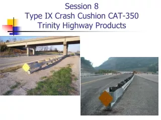
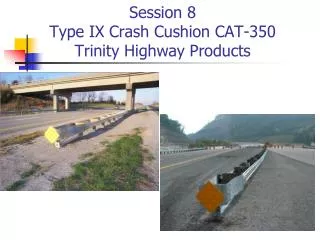
Session 8Type IX Crash Cushion CAT-350Trinity Highway Products
Installation Instructions for Proprietary Guard Rail End Terminals • Std Draw Note – RBE-200 & 205 Crash Cushion Type IX both have notes “The Manufacture SHALL furnish two (2) sets of shop plans to the contractor with each installation” • Added to Sect 719.03 of 2012 Std Specs: “Proprietary end treatments SHALL be installed according to the manufacturer’s assembly or installation instructions” • Should NOT LET THE CONTRACTOR BEGIN INSTALLATION BEFORE SUPPLYING YOU WITH THESE SHOP PLANS OR INSTALLATION INSTRUCTIONS – With this training I have attempted to follow the manuals as closely as possible but you and the contractor need these documents to properly do your jobs of installing and inspection propriety guardrail end terminals
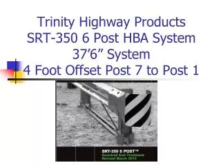
Type IX Crash Cushion CAT-350Trinity Highway Products • The CAT-350 is designed with a flimsy Nose, Breakaway Wood Post and Slotted Rail Panels that telescope through a Rectangular Plate Washer and Special Bolt Assembly that shreds the Rail Panels apart burning up the Kinetic Energy of the Crash and slowing the impacting vehicle in a controlled manner • Vehicles impacting beyond Post 4 are contained and redirected in a controlled manner – LON Begins @ Post 4
Hit Type IX CATFlimsy Nose Section crushedPost 1 & 2 Broken Off
Shredded Rail Panels after Telescoping 10 feet of Rail through Bolt Assembly
Type IX Crash Cushion CAT-350Trinity Highway Products • Kentucky utilizes the CAT-350 in Median situations where guardrail or a crash cushion is needed because the CAT has guardrail on both sides. Therefore a vehicle hitting it on the backside is hitting guardrail and not the backside of guardrail post.
Type IX Crash Cushion CAT-350Trinity Highway Products No Concrete Pad is Required
Type IX Crash Cushion CAT-350 Standard Drawings • RBB-002 Guardrail and Bridge End Drainage for Twin Structures • RBB-003 Layout of Guardrail at Twin Structures (Depressed Median) • RBE-200 Crash Cushion Type IX • RBE-205 Crash Cushion Type IX-A • RBI-007 Crash Cushion Type IX Installation at Median Piers (Depressed Median)
Key components: 1. Channel Strut 2. Cable Assembly 3. Spacer Channel 4. Restraint Rod(2) 5. Knockout Tube(2) 6. Post Plates(2) 7. Soil Tubes(6) 8. Soil Plates(6) 9. Splice Bolt Assembly 4 4 1 3 5 6 5 2 9 9 1 Each Post 7&8
Site PreparationStandard Drawing RBI-007 This Point Same Elevation As Inside Pavement Edge
Site PreparationGrading too steep – not 12:1 MinInlet too close What could we have done differently here?
Grading too steep – Note 6 RBI-007 Pavement & Grade Under Rail Same Elev.
Per Bill Gulick “You CANNOT Disconnect Grading and Guardrail”
Installation of Soil Tubes and Soil Plates • KY Uses the 6 Post CAT-350 with 6 Soil Tubes with Soil Plates • The Soil Plates are placed on the downstream side of the post • Soil tubes and soil plates can be driven in permeable soil or if impermeable soil placed in 12” drilled hole with slots for soil plates cut by hand with a rock bar
Installation of Soil Tubes and Soil Plates • Post are spaced @ 6’3” on centers • Soil Tubes must be less than 4” above finished grade • If rock is encountered see manufactures instructions
Post Placement • Post are only 3’6” long due to Soil Plates • Notched side of Post 1 faces Post 2 • Place Pipe Sleeves for Cable Assembly in Post 1 & 2 before placement • Post 1 & 2 are not secured to the Soil Tube until the Strut is placed • Post 3-6 are secured to the Soil Tube with a 5/8” x 9 ½” Hex Bolt & Nut • DO NOT overtighten bolts and deform Tubes
Installing the Strut • Bolt goes through Strut, Soil Tube and the Wood Post • A washer is placed between the Bolt head and the Strut and the Nut and the Strut • DO NOT OVERTIGHTEN bolts and deform Soil Tubes
Strut Bolt to Tight (slightly)Deforming Side of Soil TubeNo Washers
Installing the Wood Blockouts and Guardrail • NO Rail to Post connections at Post 3, 5 and 6 • @ Post 3, 5 and 6 Attach 2 Blockouts to each Post with two 5/8” x 24” Bolts and Nuts with Washers under the Bolt Head and the Nut • Two 10 Gage Slotted Rail Panels between Post 4 & 6 with plates welded to the backside on one end. Welded Plates placed at Post 4. • Panels are lapped to outside of rail at Post 6 to allow for Telescoping of the Rail Panels
Welded Plates on 10 Gage Rail Panel Placed at Post 4 with 12 Gage Rail Lapped over the 10 Gage Rail
Installing the Wood Blockouts and Guardrail • Connect Welded Plates of 10 Gage Rail with 2 Wood Blockouts to Post 4 with 2 - 5/8” x 24” Hex Bolts and Nuts with Washers under the Bolt Head and the Nut • 12 Gage Slotted Rail Panels positioned 8¼” long slots at Post 4, the four (4) ¾” diameter holes are positioned at Post 2 • 12 Gage Slotted Rail Panels are lapped outside of the 10 Gage Rail at Post 4 so it can Telescope Properly
Welded Plates on 10 Gage Rail Panel Placed at Post 4 with 12 Gage Rail Lapped over the 10 Gage Rail
Installing the Wood Blockouts and Guardrail • Rail splice @ Post 6 - Eight Plate Washers (top and underside of rail) and 8 SPECIAL 5/8” x 1¾” Bolts with “CAT” on the Bolt Head • Special Splice Bolts (Top 1” unthreaded with “CAT” on the top of the bolt) are utilized to allow Telescoping Action • DO NOT SUBSTITUTE Bolts with “CAT” on the Bolt Head – these Bolts are necessary to allow the Rail to Telescope upon impact
Special CAT Bolts and Plate Washer Connection (Top and Bottom)@ Post 6 & Properly Lapped
Close up photo of the Special CAT Splice Bolt with “CAT” on top
Installing the Wood Blockouts and Guardrail • Rail splice @ Post 4 - Eight Plate Washers (top and underside of rail) and 8 SPECIAL 5/8” x 1¾” Bolts with “CAT” on the Bolt Head • Special Splice Bolts (Top 1” unthreaded with “CAT” on the top of the bolt) are utilized to allow Telescoping Action • DO NOT SUBSTITUTE Bolts with CAT on the Bolt Head – these Bolts are necessary to allow the Rail to Telescope upon impact
12 Gage Rail Panels Lapped over 10 Gage Rail Panels @ Post 4 with Special CAT Bolt and Rectangular Washer Connection
Splice Bolt Assembly Rectangular Washers on Top and Backside of Rail Panels
Panels are suppose to be lapped to outside of rail at Post 4 & 6 to allow for Telescoping of the Rail Panels Improperly Lapped Cannot Telescope. The Rail will Bind Up & NOT Perform Properly
Installing the Wood Offset Blocks and GuardrailSpacer Channel @ Post 2 • Attach the rail at Post 2 with 2 Wood Offset Blocks, using a 5/8” X 25” Post Bolt 2 Rectangular Washers and a Hex Nut • Before tightening the Rails and Offset Blocks to Post 2, install the Spacer Channel with 8 Bolts and Nuts between the rails downstream from post 2. Locate the Spacer Channel so that brace with the 1¼” diameter hole is closest to Post 2
Spacer Channel @ Post 2 Note Blockouts are loose – not properly Nailed @ Top
Post 1-3 Spacer Channel @ Post 2 and Restraint Rod @ Post 3 Spacer Channel Restraint Rod
Assembling the Nose Section • Bolt the Side Plates to the end of each 12-Gage Rail Panel • Place the Tube Sleeve over Post 1 (Notched Post) • Nose Section is attached to Post 1 using a 5/8" X 25" post bolt • Narrow Wood Offset Blocks are placed between the Nose Section and the post
Assembling the Nose Section Continued • Rectangular Washers are placed between the 5/8” x 25” Post Bolt Head and Nose Section and the Hex Nut and the Nose Section. Excess threads should be cut off and peened. • Bolt the Nose Section to the side plates, using eight 5/8" X 1- ¼ “ Slice Bolts and Hex Nuts
Nose section Bolted to the Side Plates and 5/8” x 25” Bolt with Rectangular Washer @ Post 1
Nose Section in Place With Nose Section Bolted to the Side Plates & Post 1 Side Plates Bolted to Rail
Installing the Cable Anchor Assembly • Slide one end of the Cable through the Pipe Sleeve at the base of Post 1. • Place the Bearing Plate over the cable stud with the 5” dimension up and the 3” down • Place a Washer and Nut over the end of the Cable Assembly and tighten • Prevent the bearing plate from rotating by driving two nails along its top edge and bending them over
Bearing Plate not oriented properly (5” not up) and not Nailed @ Top Does have Double Nut & Washer Bearing Plate with 2 bent nails preventing rotation
Installing the Cable Anchor Assembly • Slide the other end of the Cable through the Pipe Sleeve at the top of Post 2 and then through the 1¼” diameter hole in the Spacer Channel • Place a 1” Washer over the end of the Cable Assembly and secure with a Nut and tighten on this end • Restrain the cable with vise grips to avoid twisting the cable
Installing the Cable Anchor Assembly • After tightening a second Nut is added to each end of the Cable Assembly to prevent loosening