Download
1 / 21
210 likes | 397 Views
From MDI to HMI. Outline. MDI Status HMI Overview Observing scheme Status Schedule Transition. MDI Status. 10 year launch anniversary Dec 2! 100 million exposures Keyhole Broken antenna Flip every 3 months Loose two weeks of high rate data Difficult to get good dynamics runs

E N D
Outline • MDI Status • HMI • Overview • Observing scheme • Status • Schedule • Transition
MDI Status • 10 year launch anniversary Dec 2! • 100 million exposures • Keyhole • Broken antenna • Flip every 3 months • Loose two weeks of high rate data • Difficult to get good dynamics runs • Otherwise things are fine • Plan to operate for 6-12 months after HMI is operational • Other SOHO instruments may be kept running after that
HMI Overview • The primary goal of the Helioseismic and Magnetic Imager (HMI) investigation is to study the origin of solar variability and to characterize and understand the Sun’s interior and the various components of magnetic activity. • The HMI investigation is based on measurements obtained with the HMI instrument as part of the Solar Dynamics Observatory (SDO) mission. • HMI makes measurements of several quantities • Doppler Velocity (13m/s rms.) • Line of sight (10G rms.) and vector magnetic field • Intensity • All variables all the time with 0.5” pixels • Most at 50s or better cadence • Variables are made from filtergrams, all of which are downlinked • Higher level products will be made as part of the investigation. • All data available to all. • Launch in August 2008. 5 Year nominal mission. • Education and Public Outreach program included.
Instrument Overview • Optics Package • Telescope section • Polarization selectors – 3 rotating waveplates for redundancy • Focus blocks • Image stabilization system • 5 element Lyot filter. One element tuned by rotating waveplate • 2 Michelson interferometers. Tunable with 2 waveplates and 1 polarizer for redundancy • Reimaging optics and beam distribution system • Shutters • 2 functionally identical CCD cameras • Electronics package • Cable harness
¼ Waveplate ½ Waveplates Image Stabilization Mirror Beam Control Lens Aperture Stop Blocking Filter Telescope lens set Wideband Michelson Telecentric Lens Lyot Polarizer Tuning Waveplates Calibration lenses and Focus Blocks Narrowband Michelson ISS Beamsplitter and Limb Tracker Assembly BDS Beamsplitter Front Window Filter Relay Lens Set CCD Shutter Assemblies CCD CCD Fold Mirror Fold Mirror CCD Fold Mirror Instrument Overview – Optical Path Filter Characteristics: Central Wave Length: 613.7 nm FeI Front Window Rejects 99% Solar Heat Load Bandwidth: 0.0076 nm Tunable Range: 0.05 nm Free Spectral Range: 0.0688 nm Optical Characteristics: Focal Length: 495 cm Focal Ration: f/35.2 Final Image Scale: 24m/arcsec Primary to Secondary Image Magnification: 2 Focus Adjustment Range: 16 steps of 0.4 mm
Instrument Overview – HMI Optics Package (HOP) Connector Panel Z Focal Plane B/S Fold Mirror Shutters Alignment Mech X Limb Sensor Y Oven Structure Detector Michelson Interf. Lyot Filter CEBs Detector Vents Limb B/S Front Window Active Mirror Polarization Selector Focus/Calibration Wheels OP Structure Mechanical Characteristics: Box: 0.84 x 0.55 x 0.16 m Over All: 1.19 x 0.83 x 0.29 m Mass: 39.25 kg First Mode: 63 Hz Telescope Support Legs (6) Front Door
Observing Scheme • Observables • Dopplergrams • Magnetograms, vector and line of sight • Others: Intensity, line depth, etc. • Observables made from filtergrams described by framelists • Filtergram properties • Wavelength – selected by rotating waveplates (polarizer for redundancy only) • Polarization state – selected by rotating waveplates • Exposure time • Camera ID • Compression parameters, … • Determined by subsystem settings • E.g. motor positions • Framelists • Fixed list of filtergrams repeated at fixed cadence during normal operations • Entirely specified in software – highly flexible
Observables Calculation • Make I, Q, U, V, LCP, RCP • Linear combinations of filtergrams • Correct for flat field, exposure time and polarization leakage • Correct for solar rotation and jitter (spatial interpolation) • Sun rotates by 0.3 pixels in 50s! • Interpolation necessary • Fast and accurate algorithm exists • Correct for acceleration effects (temporal interpolation) • Nyquist criterion almost fulfilled for Doppler and LOS • Nyquist is grossly violated for vector measurements in case of long framelists • Significant improvement from interpolation • Clever tricks exist • Temporal averaging helps • Fill gaps • Data loss budget gives missing data in every filtergram! • Various algorithms exist • May do nothing for vector field • What do the users prefer?
Observables Calculation • Average in time, if desired • Done for at least some vector field inversions • Calculate observables • MDI-like and/or least squares for Doppler and LOS? • Fast and/or full inversion for vector field • Many challenges remain • Calibration, code development, etc. • Community input needed! • Inversion codes • Which dataproducts do you want? • Science
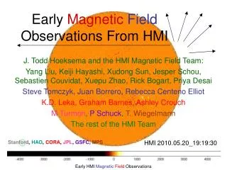
Status – What I hoped to show • First HMI Dopplergram
Status • First set of Michelsons in house • Optics and filters in house • Some spares still to be delivered • Several flight 4096x4096 CCD’s in house • Instrument being assembled • May see first light before Christmas • Mechanisms • Shutters and HCMs finished life test successfully • Electronics at various stages • Significant delays expected • Instrument software at various stages • Ground software at various stages
Status - Integration Flight Michelsons Flight Structure Heater Wiring Primary & Secondary Lens Assemblies Telescope Assembly on Alignment Plate
Status - Integration ISS Fold Mirror Assembly ISS Mirror Assembly ISS Sensor Assemblies BDS Fold Mirror Assembly BDS Fold Mirror Assembly CCD Fold Mirror Assembly
Schedule • Late 2005: First Sun test • Feb 2006: Team meeting • Summer 2006: Final instrument tests • Feb 2007: Instrument delivery • Aug 2008: Launch • Nov 2008: Begin science observations • Nov 2013: End of science observations • Nov 2014: End of mission • Stay tuned on http://hmi.stanford.edu !
MDI -> HMI Transition • Basically we will get 6-12 months of overlap • Any particular things we should do during that period? • Anything we need to do now?
Summary • 4096x4096 full disk coverage • 0.5” pixels • Continuous coverage • Doppler and LOS at 40s cadence • Vector magnetograms at 40s-120s cadence • Uniform quality • Same observing sequence all the time • August 2008 launch • 5 year nominal mission • Lots of new science possible • Need your help!
Filter profiles Line profile MDI Continuum Continuum