Download
1 / 16
160 likes | 262 Views
Necessidade de um Meio de Comunicação Concorrente. Controle Calibração Monitoramento/Debug VME Bus Alta Taxa de Dados Evitar Overhead Independência entre os barramentos. CAN(Controller Area Network) Bus. Estrutura de Rede Imunidade à RuÃdo NRZ Tratamento de Erros no hardware.

E N D
Necessidade de um Meio de Comunicação Concorrente • Controle • Calibração • Monitoramento/Debug • VME Bus • Alta Taxa de Dados • Evitar Overhead • Independência entre os barramentos
CAN(Controller Area Network) Bus • Estrutura de Rede • Imunidade à Ruído • NRZ • Tratamento de Erros no hardware • ISO-11898: • Alta Velocidade(125 Kbps – 1Mbps) • L<=40m @ 1 Mbps, n<=30 • L<=1000m @ 62.5 Kbps, n<=120
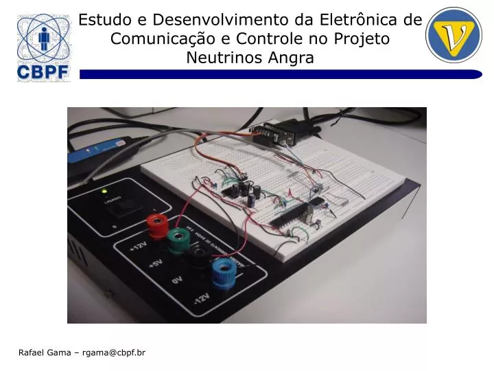
CAN Interface Rafael Gama – rgama@cbpf.br
CAN Interface • 1) Transceiver • ISO-88198 • Disponibilidade • Solução Microchip • 2) MCU • CAN 2.0B • Disponibilidade • PIC18 – 8 bits • Custo
Transceiver • Hi Z • n<=112 • Um node sem alimentação ou em falha não pertuba o bus • Proteção: curto-circuito, sobretensão, falha no aterramento, ESD, temperatura • Controle Slew Rate, <RFI
Microcontrolador • 8 bits CPU @ <= 40 MHz • PLL 4x • 64Kbytes Flash (Programa) • 1Kbyte EEPROM • SPI • UART • Sleep
Programação do Firmware • 1)Crate • VME Bus • 2)Standalone • ICSP • USB
Node 1: Interface CAN do Protótipo 1)CAN Transceiver 2)MCU 3)RS232 Transceiver
Node 2: Kvaser Leaf HS • CAN 2.0B • ISO-11898 • Texas SN65HVD251 • 5Kbits/s – 1Mbit/s • USB: 12 Mbits/s • Precisão do Clock: 100ms • Taxa de Mensagens: 8000 Mensagens/s
Protótipo: Fotos • MCU (PIC18F2680) • CAN Transceiver • RS232 Transceiver • Ligação da Interface CAN – Protótipo no CAN bus • RS232 do PC-AT • CAN Interface – Protótipo • Kvaser Leaf HS – USB<>CAN Interface • PC-AT • Cabo: 50 metros • Ligação da Interface USB<>CAN no CAN bus
Conclusão • Referências • PIC18F2680 Data sheet, DS39625C, Disponível em www.microchip.com • MCP2151 Data sheet, DS21667, Disponível em www.microhcip.com • Controller Area Network (CAN) Basics, AN713, DS00713, Disponível em www.microchip.com • Interfacing High Speed ADCs via SPI User Manual, AN877, Disponível em www.analog.com • Debugging Serial Buses in Embedded System Designs, 48W-19040-4 (WebID: 12641), Disponível em www.tek.com • CAN Specification 2.0B, Disponível em www.semiconductors.bosch.de • Kvaser Leaf User Guide, Last Updated: Monday, 13 November 2006, Disponível em www.kvaser.com • Interface CAN – Protótipo • (loopback @ 125 Kbps) • Mensagens Tx:4159597 • Mensagens Rx:4159597 • Erros:0 • Etapas Futuras • Teste com dispositivos SPI • Teste com vários nodes