Download
1 / 5
70 likes | 135 Views
With the change of the informatics proprietary system to open system were created for the change of proprietary cable system to open system of common use arising then the concept of structured cabling network. These are system to interconnect devices allowing for sharing resources peripherals and other information.

E N D
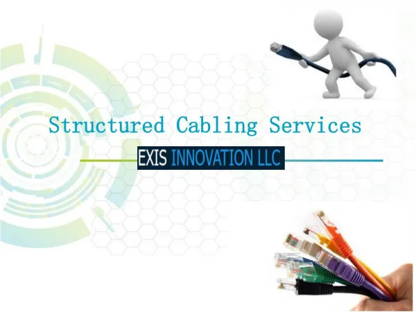
Copper and optical fibre structured cabling networks With the change of the informatics proprietary system to open system were created for the change of proprietary cable system to open system of common use arising then the concept of structured cabling network. These are system to interconnect devices allowing for sharing resources peripherals and other information. A network designed and installed properly will give the speed and reliability essential to the efficiency system. Once the phones were the only concern, but now we must deal with the demanding requirements are expanding constantly, you must specify and plan networks that can grow or be modified at any time; an integrated network of voice and data must be structured i.e. it should be generic cabling system that uses approach of the distribution for work areas. The patch panels located in the racks of the technical room allows PC, printers, telephones and other equipment to be connected or disconnected easily and quickly and that all necessary changes made only in the rack not requiring changes in the path ways of the cables and associated wiring. The structured cabling system have been developed to reduce the costs of these chances. Unstructured systems usually have a lower initial cost than a well structured system, but this is a glaring example of how the cheap comes out expensive. The proof of the success of these systems is the increasing involvement of regulation entities in the normalization of new networks based on this model, since the regulations ITED and ITUR are the best examples of this practise in Portugal. The existing structured cabling systems have a wide range of adapters that allow continuing to use old equipment and go adding the latest communication technologies that will become available space in the cabinet and their path ways. The structured cabling network are building or campus communications cabling infrastructure that consist of a set of standardized smaller elements called subsystems. Subsystems: •Structured cabling are divided into six subsystems: •Entrance interfaces are the interfaces with the outside world •Equipment room is a room where the equipment which serve the user are hosted •Communications Room room that house the communication equipment which connect the backbone and the horizontal cabling subsystem. •Backbone cabling is a cabling that is connected to the between the entrance interface, the equipment •Room and the communication room •Horizontal cabling connect communications room to terminal outlets •Terminal components connects end user equipments to terminal outlets of the horizontal cabling Copper Cable Categories: In the horizontal distribution wiring is used UTP, FTP and STP cable type, which fall under one of the following categories: •Cat.3 currently defined in TIA/EIA 568 B used for data network using frequencies upto 16 MHz. Historically popular for telephone and 10 M bit/s Ethernet networks using TVHV cable type. Currently in Portugal you may not use such cables in horizontal distribution they can be used only in telephones networks backbones. •Cat.5e currently defined in TIA/EIA 568-B for networks upto 100 MHz, is used for 100 Mbit/s Ethernet works.
•Cat.6 Currently defined in TIA/EIA-568-B for networks up to 250 MHz, more than double category 5e; suitable for 1000BASE-T Gigabit Ethernet networks •Cat.6a Currently defined in ANSI/TIA/EIA-568-B.2-10 for networks up to 500 MHz, double that of category 6. Suitable for 10GBase-T networks; •Cat.7 An informal name applied to ISO/IEC 11801 Class F cabling for networks up to 600 MHz. This standard specifies four individually-shielded pairs inside an overall shield; •Cat.7a An informal name applied to Amendment 1 of ISO/IEC 11801 Class F cabling for networks up to 1000 MHz. Cables and Installations: Structured cabling design and installation is governed by a set of standards that specify how wiring data centres, offices and apartment buildings for data, video and voice communications using cable and modular sockets. These standards define how to lay the cabling in a star formation, such that all outlets terminate at a central patch panel, which is normally 19 inch rack-mounted, from where it can be determined exactly how these connections will be used. Each outlet can be “patched” into a data network switch (normally also rack mounted), or patched into a “telecoms patch panel” which forms a bridge into a PABX (private automatic branch exchange) telephone system, thus making the connection to a voice port. Structured cabling networks uses the following types of cable: •UTP (unshielded twisted pair) •FTP (foiled twisted pair) •STP (shielded twisted pair) •Optical Fibre UTP – Unshielded Twisted Pair UTP cables are found in most Ethernet networks and telephone systems and are mostly made of 4 pairs. Is the most common cable used in structured networking because of its relatively lower costs compared to optical fibre and coaxial cable. UTP is also finding increasing use in video applications, primarily in security cameras – much of the middle to high-end IP cameras include a UTP output with setscrew or socket terminals (RJ45) – this is made possible by the fact that UTP cable bandwidth has improved to match the baseband of television signals.
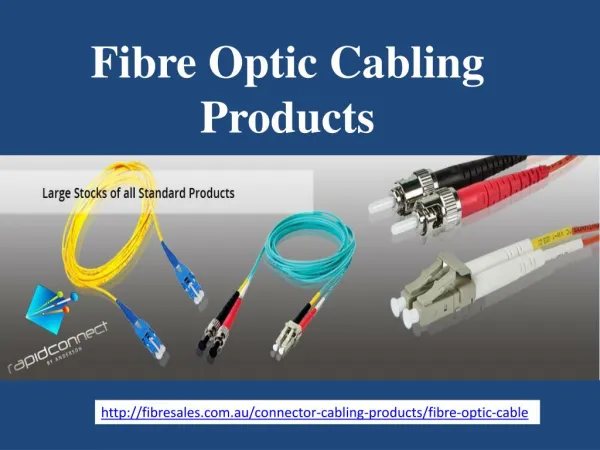
FTP - Foiled Twisted Pair FTP cables are screened UTP cables. STP – Shielded Twisted Pair STP cabling includes metal shielding over each individual pair of copper wires. This type of shielding protects cable from external EMI (electromagnetic interferences). There are also S/STP cables that is both individually shielded (like STP cabling) and also has an outer metal shielding covering the entire group of shielded copper pairs (like FTP). This type of cabling offers the best protection from interference from external sources, and also eliminates alien crosstalk. Note: FTP, STP and S/STP cable shields have to be well grounded (less then 3 ohm ground resistance) to avoid “aerial effect” – this phenomena increase external electromagnetic interferences – a shield not grounded acts as an aerial. Optical fibre An optical fibre is a glass or plastic fibre that carries light along its length. It is the combination of science and engineering towards the practical application of knowledge in optical sciences to communications. Optical fibres are widely used in communications because they permit transmission over longer distances and at higher bandwidths (data rates) than other forms of communications. Fibers are used instead of metal wires because signals travel along them with less loss and they are also immune to electromagnetic interference.
The generally accepted splicing fibre method is arc fusion splicing, which melts the fiber ends together with an electric arc. Fusion splicing is done with a specialized instrument that typically operates as follows: •The two cable ends are fastened inside a splice enclosure that will protect the splices and the fiber ends are stripped of their protective polymer coating (as well as the sturdier outer jacket, if present). •The ends are cleaved (cut) with a precision cleaver to make them perpendicular and are placed into special holders in the splicer. The splice is usually inspected via a magnified viewing screen to check cleaves before and after the splice. •The splicer uses small motors to align the end faces together and first emits a small spark between electrodes, at the gap, to burn off dust and moisture; then the splicer generates a larger spark that raises the temperature above the melting point of the glass, fusing the ends together permanently. The location and energy of the spark are carefully controlled so that the molten core and cladding do not mix minimizing optical loss. A splice loss estimate is measured by the splicer, by directing light through the cladding on one side and measuring the light leaking from the cladding on the other side. A splice loss under 0.1 dB is typical. The complexity of this process makes fibre splicing much more difficult than splicing copper wire. With multimode fibre (not acceptable with single mode fibre) and for quicker fastening jobs, a "mechanical splice" is used: •Mechanical fibre splices are designed to be quicker and easier to splice, but there is still the need for stripping, careful cleaning and precision cleaving. •The fibre ends are aligned and held together by a precision-made sleeve, often using a clear index-matching gel that enhances the transmission of light across the joint. •Such joints typically have higher optical loss and are less robust than fusion splices. Various polish profiles are used, depending on the type of fiber and the application: •The fibre ends are typically polished with a slight curvature, such that when the connectors are mated the fibres touch only at their cores – this is known as a "physical contact" (PC) polish. •The curved surface may be polished at an angle, to make an "angled physical contact" (APC) connection - such connections have higher loss than PC connections, but greatly reduced back reflection because light that reflects from the angled surface leaks out of the fiber core; the resulting loss in signal strength is known as gap loss – APC fiber ends have low back reflection. Advantages over other integrated data and power standards This technology is especially useful for powering IP telephones, wireless LAN access points, IP cameras with pan tilt and zoom (PTZ), remote Ethernet switches, embedded computers, thin clients and LCD monitors. All these require more power than USB offers and very often must be powered over longer runs of cable than USB permits. In addition, PoE uses only one type of connector (8p8c RJ45) whereas there are four different types of USB connectors. PoE is presently deployed in applications where USB is unsuitable and where AC power would be inconvenient, expensive or infeasible to supply.
However, even where USB or AC power could be used, PoE has several advantages over either, including the following: •Cheaper cabling — even Cat.5e cable is cheaper than USB repeaters. •A Gb/s of data to every device is possible, which exceeds newer USB and the AC powerline networking capabilities. •Global organizations can deploy PoE everywhere without concern for any local variance in AC power standards, outlets, plugs or reliability of AC power. •Direct injection from standard 48 V DC battery power arrays; this enables critical infrastructure to run more easily in outages and make power rationing decisions centrally for all the PoE devices. •Symmetric distribution is possible – unlike USB and AC power, power can be supplied at either end of the cable or outlet – this means the location of the power source can be determined after cables and outlets are installed. For more details please visit the following sites: https://www.cbo-it.de https://www.gbic-shop.de/