Download
1 / 16
160 likes | 823 Views
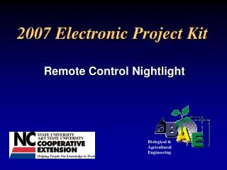
2007 Electronic Project Kit Remote Control Nightlight Biological & Agricultural Engineering Objectives Learn to read and follow an electric schematic Identify electronic circuit components Function of circuit components How to solder correctly Promote Science and Technology

E N D
2007 Electronic Project Kit Remote Control Nightlight Biological &Agricultural Engineering
Objectives • Learn to read and follow an electric schematic • Identify electronic circuit components • Function of circuit components • How to solder correctly • Promote Science and Technology
Safety First: How to use a soldering iron • Soldering joins metals to make an electrical and mechanical connection • Solder is an alloy of metals which can include tin, copper, silver, and lead • Soldering irons are used to melt solder and can reach temperatures of 600-700 degrees Fahrenheit
General Instructions • Refer to Figure 1 for parts layout and parts list • Refer to Assembly Instructions steps 1-7 • Suggested assembly order; • Install resistors first (especially if new to soldering) • Install diode (band up) • Install capacitor and LEDs (polarity sensitive) • Install transistors (note orientation) • Install IR Module (solder pins and large flat tabs) • Install 9V battery snap • Any TV/VCR remote will provide the IR signal to turn the LEDs on
Correct Board Orientation Top Edge Front (Component side) Back (Soldering side)
Resistors Resistors are electrical components that impede the flow of electrons. The unit of measure of resistance is the Ohm (Ω). Also refer to the color code in the instructions (Figure 6).
Diode A diode is usually made from two semiconductor materials. It causes electrons to flow in only one direction.
Capacitor A capacitor is a combination of conducting and insulating layers that has the capacity to receive, hold, and release electrons. Note that Capacitors are polarity sensitive, positive (+) and negative lead (-).
Transistors Transistors are transient resistors—they are made from semiconductor materials that enable a small current to control a larger current
Light emitting diodes (LED’s) LED’s are semiconductors that emit light in response to a small voltage without heat being produced.
LED’s – cont. • Polarity sensitive; • + Anode • Cathode (short leg) • Also refer to Figure 4 • in the instructions for • more information. Flat Side (Notch) Short Leg (-) (-) (+)
Additional Resources • 4-H Electric Curriculum Project Guide, “Entering Electronics” • “Soldering and Troubleshooting Tips” on Electric Program web page
Visit the Electric Program web site at; http://www.bae.ncsu.edu/programs/extension/4-h/index.html