Download
1 / 17
170 likes | 337 Views
Electronic Project Kit. Grant Ellington North Carolina State University. Biological & Agricultural Engineering. Objectives. Learn to read and follow an electric schematic Identify electronic circuit components Function of circuit components How to solder correctly

E N D
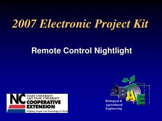
Electronic Project Kit Grant Ellington North Carolina State University Biological &Agricultural Engineering
Objectives • Learn to read and follow an electric schematic • Identify electronic circuit components • Function of circuit components • How to solder correctly • Promote Science and Technology
General Instructions • Refer to Figure 1 for parts layout and parts list • Refer to Assembly Instructions step 1-3 • Suggested assembly order; • Install resistors first (especially if new to soldering) • Install IC socket (notch down), trimmer resistor (P1) and LEDs • Solder 9V snap plus wire to switch and board • Solder thermistor to wire pair and board • Install IC Chip (notch down)
Top Edge Front Side Back Side
Resistor Provides resistance to impede the flow of current or electrical charge Limits the current in desired components of a circuit 22K Ohm 10 Ohm Variable
Resistor Value 1st = numeric value 2nd = numeric value 3rd = multiplier 4th = tolerance 1st band 4th band 2nd band 3rd band Refer to Resistor Color Code (Kit Instructions Figure 5)
Resistors Positioned Correctly R1 R2, R3 R4
Integrated Circuit (IC) Multiple circuit components processed or contained in a single substrate or chip IC Socket IC Chip
LED (Light Emitting Diode) • Emit light in response to • small voltage • Polarity sensitive; • + Anode • Cathode (short leg) Flat Side (Notch) Short Leg (-) (-) (+) Refer to LED Info (Kit Instructions Figure 4)
On-Off Switches SPST - Single Pole Single Throw Push Button Momentary Toggle SPDT - Single Pole Double Throw (3-way) DPDT - Double Pole Double Throw
Switch and 9V Battery Snap + (red) - (black)
Thermistor • Temperature sensing device; • Resistance changes with • temperature • Negative coefficient type • Limited range
Thermistor Connection Heat Shrink Tubing Solder to board
Additional Resources • 4-H Electric Curriculum Project Guides • Entering Electronics • “Soldering and Troubleshooting Tips” on Electric Program web page