Download
1 / 5
50 likes | 60 Views
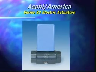
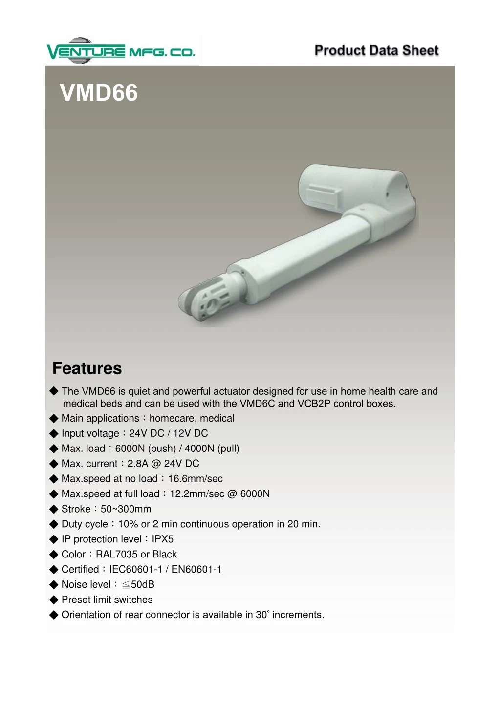
The VMD66 is another new series of actuators added to our lineup. These actuators are quiet, powerful and dependable. They were specifically designed for medical and home health care applications.

E N D
VMD66 Features ◆ The VMD66 is quiet and powerful actuator designed for use in home health care and medical beds and can be used with the VMD6C and VCB2P control boxes. ◆Main applications:homecare, medical ◆Input voltage:24V DC / 12V DC ◆Max. load:6000N (push) / 4000N (pull) ◆Max. current:2.8A @ 24V DC ◆Max.speed at no load:16.6mm/sec ◆Max.speed at full load:12.2mm/sec @ 6000N ◆Stroke:50~300mm ◆Duty cycle:10% or 2 min continuous operation in 20 min. ◆IP protection level:IPX5 ◆Color:RAL7035 or Black ◆Certified:IEC60601-1 / EN60601-1 ◆Noise level:≦50dB ◆Preset limit switches ◆Orientation of rear connector is available in 30° °increments.
Options ◆Positioning signal feedback with Hall effect sensor X1 ◆Positioning signal feedback with Hall effect sensor X2 ◆Safety Nuts ◆Push only Compatibility 1. Control box Without positioning feedback VCB2P、VCB4P、VMD6C、VMD7C、VCBP2 Positioning signal feedback with Hall effect sensor x 1 Positioning signal feedback with Hall effect sensor x 2 VCB4P-HP-SY VCB4P-SY-CG-BA VMD6C & VCB2P can be easily fixed onto VMD66 actuator VMD66 shown with VCB2P VMD66 shown with VMD6C Pin Assignment 2. Accessory None
Performance Data Speed (mm/s) Current (A) Push Pull Model No. No load Full load Max. (N) Max. (N) No load Full load 12V 24V 12V 24V 6000 4000 1.2 0.6 5.2 2.6 4.1 2.8 VMD66-XX-F3-XXX.XXX 6000 4000 0.8 0.4 5.4 2.7 4.2 2.9 VMD66-XX-A4-XXX.XXX 5000 4000 0.8 0.4 5.6 2.8 5.5 4.4 VMD66-XX-F4-XXX.XXX 4000 4000 0.4 0.2 5.0 3.0 6.2 3.8 VMD66-XX-A6-XXX.XXX 3000 3000 1.0 0.5 5.6 2.8 8.2 6.6 VMD66-XX-F6-XXX.XXX 3000 3000 0.6 0.3 5.4 2.7 8.3 5.0 VMD66-XX-A8-XXX.XXX 3000 3000 1.0 0.5 5.8 2.9 11.0 8.2 VMD66-XX-F8-XXX.XXX 1500 1500 16.6 12.2 0.4 0.2 5.6 2.8 VMD66-XX-AG-XXX.XXX
Dimensions ◆Front Connector ◆Rear Connector ~300mm ◆Available stroke (S) range = 50~ ◆Retracted length (A) Front connector = C3x, C4x, C7x ≧ ≧ stroke + 160mm Front connector = C1x, C6x, C8x ≧ ≧ stroke + 188mm Safety Nut : additional 8mm is required ◆Extended length (B) = S+A
Ordering Key VMD66—□□—□□—□□□ —□□—□□—□□□.□□□— □□□—C□□—□□□ □□—□□□ Input Voltage 12: :12V DC 24: :24V DC Motor and Spindle Code A4、 、A6、 、A8、 、AG、 (Refer to paragraph Performance Data) 、F3、 、F4、 、F6、 、F8 Retracted Length (Refer to paragraph Dimensions) Extended Length (=Retracted length + Stroke. Refer to paragraph Dimensions) Front Connector 1: :Plastic 4: :Oval hole 7: :Nylon bushing 3: :Round hole 6: :Enhanced plastic 8: :Metal Rear Connector 2: :Aluminum alloy Options HS3: :Hall sensor x 1 HS4: :Hall sensor x 2 PO: :Push only SN: :Safety nut Terms of Use The user is responsible for determining the suitability of Venture products for specific applications. Due to continuous development in order to improve its products, Venture products are subject to frequent modifications and changes without prior notice. Venture reserves the right to discontinue the sale of any products displayed on its website or listed in its catalogue or other written materials drawn up by Venture Mfg. Co.