Download
1 / 38
390 likes | 415 Views
Small-scale Mobile radio propagation. Small scale propagation implies signal quality in a short distance or time range In this small range, fading or rapid fluctuation of the signal amplitude is observed

E N D
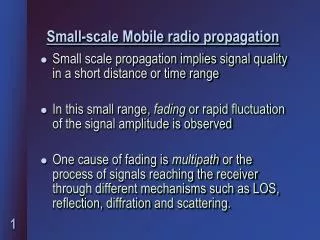
Small-scale Mobile radio propagation • Small scale propagation implies signal quality in a short distance or time range • In this small range, fading or rapid fluctuation of the signal amplitude is observed • One cause of fading is multipath or the process of signals reaching the receiver through different mechanisms such as LOS, reflection, diffraction and scattering.
Multipath effects • Rapid changes in signal amplitude over a small distance or time interval. • Rapid changes in signal phaseover a small distance or time interval. • Time dispersion (echoes) caused by multipath propagation delay.
Causes of fading • In urban areas, fading occurs because the height of mobile is lesser than the height of surrounding structures, such as buildings and trees. • Existence of several propagation paths between transmitter and receiver.
Factors influencing small signal fading • Multipath propagations • Speed of mobile (Doppler shift) • Speed of surrounding objects • Bandwidths of signal and channel
Analysis of multipath channel Receiver Transmitter Spatial position d
Convolution model for multipath signal Received signal: y(t) = A0 x(t) + A1 x(t - t1) + A2 x(t - t2) + ... A2 x(t- t2) LOS T R, y(t) , x(t) A1 x(t- t1)
System definition of multipath h(t) x(t) y(t)
Baseband signal definition x(t) = c(t) cos (2fct ) • Transmitted signal c(t)- pulse • Received signal y(t) = r(t) cos (2fct )
Base band equivalent channel hb(t) c(t) r(t)
Modeling of the baseband multipath model r(t) = c(t) * hb(t, t) • Mathematicalmodel hb(t,t) t3 t2 t1 t0 tot1t2 tN-2 tN-1
Excess delay concept • The delay axis t, to<= t <= tn-1 is divided into equal time delay segments called excess delay bins. t0 = 0 t1 = t t2 = 2 t tN-1 = (N-1)t
Delay component design • All multipath signals received within the bins are represented by a single resolvable multipath component having delay ti. • Design equation for bin width t: Bandwidth of signal = 2/t
Final model for multipath response N-1 ji r(t) = ai e c[t –ti] i = 0 • c(t) – Transmitted pulse • r(t) – Received pulse • N – Number of multipaths • ai– Amplitude of multipath i • qi – Phase of multipath i • ti– Time delay of multipath i
Wideband multipath signals N-1 j i Received signal r(t) = ai e p[t–ti] i = 0 Instantaneous received power: N-1 |r(t)|2 = |ak|2 k = 0 =>Total received power = sum of the power of individual multipath components.
Narrowband multipath signals N-1 ji Received signal: r(t) = aie p[t–ti] i = 0 Instantaneous received power: N-1 ji |r(t)|2 = | aie |2 i = 0
Conclusions • When the transmitted signal hasa wide bandwidth >> bandwidth of the channel, multipath structure is completely resolved by the receiver at any time and the received power varies very little. • When the transmitted signal has a very narrow bandwidth (example the base band signal has a duration greater than the excess delay of the channel) then multipath is not resolved by the received signal and large signal fluctuations occur (fading).
Example Assume a discrete channel impulse response is used to model urban radio channels with excess delays as large as 100 s and microcellular channels with excess delays not larger than 4 s. If the number of multipath bins is fixed at 64 find: (a) t (b) Maximum bandwidth, which the two models can accurately represent.
Solution For urban radio channel Maximum excess delay of channel tN = N t = 100 s. N = 64 t = tN /N = 100 s /64 = 1.5625 s Maximum bandwidth represented accurately by model = 2/ = 1.28 MHz
For microcellular channel Maximum excess delay of channel tN = N t = 4 s. N = 64 t = tN /N = 4 s /64 = 62.5 ns Maximum bandwidth represented accurately by model = 2/ t = 32 MHz
Small-scale multipath measurements • Direct Pulse Measurements • Spread Spectrum Sliding Correlator Measurement • Swept Frequency Measurement
Types of Small Scale Fading Doppler Spread Multipath time delay Slow fading Fast Fading Flat fading Frequency Selective Fading
Mechanisms that cause fading • 2 main propagation mechanisms: • Multipath time delay spread • Doppler spread • These two mechanisms are independent of each other.
Multipath terms associated with fading Ts = Symbol period or reciprocal bandwidth Bs = Bandwidth of transmitted signal Bc= Coherence bandwidth of channel Bc= 1/(50)where is rms delay spread
Calculation of Delay Spread __ _ 2 = 2 - ( )2 Where: _ = ( ak2) / ( ak2) __ 2 = ( ak22) / ( ak2)
Fading effects due to Doppler spread fc = frequency incident signal Received signal spectrum = fc+/- fd fd = Doppler shift fc V
Doppler spread and coherence time Doppler frequency shift: fd = (v / ) cos , Wavelength = c / fc Maximum Frequency deviation = fm = v / Doppler Spread BD = fm Coherence time = Tc = 0.423 / fm
Mathematical estimation of fading Flat fading • Mobile channel has constant gain and linear phase response. • Spectral characteristics of the transmitted signal are maintained at receiver • Condition: Bs<< Bc => Ts >>
Frequency selective fading • Mobile channel has a constant gain and linear phase response over a finite bandwidth • Condition: Bs> Bc => Ts <
Flat fading or frequency selective fading? Common rule of thumb • If Ts ≥ 10 => Flat fading • If Ts < 10 => Frequency selective fading
Fast fading channel • The channel impulse response changes rapidly within the symbol duration. • This causes frequency dispersion due to Doppler spreading, which leads to signal distortion. • Condition: Ts > Tc Bs < BD
Slow fading channel • The channel impulse response changes at a much slower ratethan the transmitted signal • Velocity of mobile (or velocity of objects in channel) • Condition: Ts < Tc Bs > BD
Rayleigh and Ricean distributions • In mobile radio channels, the Rayleigh distribution is commonly used to describe the statistical time varying nature of the received fading signal • When there is a dominant (non-fading) signal component present such as LOS propagation path, the small scale fading envelope distribution is Ricean
Level crossing and fading statistics • Level crossing rate (LCR) Rate at which the normalized Rayleigh fading envelope crosses a specified level in a positive going direction. LCR = NR= (2)fme-2 fm= Maximum Doppler frequency = R/Rms = specified level R, normalized to the rms value of fading signal
Average fade duration Average period of time for which the received signal is below a specified level R. __ • = e2– 1 ________ fm2
Example (a) For a Rayleigh fading signal, compute the positive going level crossing rate for = 1, when the maximum Doppler frequency, fm, is 20 Hz. (b) What is the average fade duration?
Solution = 1 fm = 20 Hz (a) Number of zero level crossings is: NR = 2 (20) e-1 = 18.44 Crossings/Sec Maximum velocity of mobile = fd = 20 (3 X 10⁸)/(900X106) = 6.66 m/s
(b) Average fade duration __ • = e2– 1 ________ fm2 • = e1– 1 ________ = 0.034 s 1x 202p
Statistical methods for fading channels • Clark’s model for Flat Fading • Two-Ray Rayleigh Fading Model • Saleh and Valenzuela Indoor statistical Model • SIRCIM (Simulation of Indoor Radio Channels Impulse Response Models) • SMRCIM (Simulation of Mobile Radio Channel Impulse-Response Models)