Download
1 / 85
870 likes | 1.08k Views
Runway Length Analysis & Apron Layout Design. Presented To: Central Region Airports Conference By: Todd M. Madison, P.E. Jeff Deitering, P.E. Date: Wednesday, September 23, 2009. Introduction. Runway Length Critical Design Aircraft Part 77 Consideration Utility vs. Other Than Utility

E N D
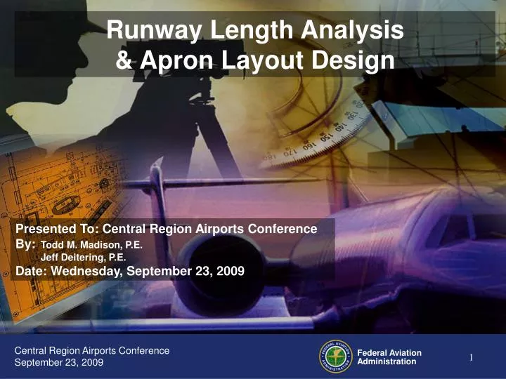
Runway Length Analysis & Apron Layout Design Presented To: Central Region Airports Conference By: Todd M. Madison, P.E. Jeff Deitering, P.E. Date: Wednesday, September 23, 2009
Introduction • Runway Length • Critical Design Aircraft • Part 77 Consideration • Utility vs. Other Than Utility • Approach Procedure Type • AC 150/5325-4B • Chapter 2, Small Aircraft • Chapter 3, Business Jets/Large aircraft • Chapter 4, RJs and Heavies • AC 150/5300-13, Change 14 • Apron Layout • Guidance • Tools • Design Criteria • Marking Plan • Examples • Turnarounds
Critical Design Aircraft FAIL TO PLAN, PLAN TO FAIL.
Critical Design Aircraft • Established in Master Plan (or Narrative Report) • The most demanding aircraft identified in the forecast that will use the airport. • Have at least 500 or more annual itinerant operations at the airport (landings and takeoffs are considered as separate operations) for an individual airplane or a family grouping of airplanes. • Derived from Approved Forecast • Existing Critical Design Aircraft based on 1 to 5 year (Short Term) Forecast • Future/Ultimate Critical Design Aircraft based on 6 to 20 year (Intermediate/Long Term) Forecast • See AC 150/5325-4, 102.a.(8) and AC 150/5070-6, 702.a.
Part 77 Considerations • Utility Runway • Pavement strength less than 12,500 pounds for Single Wheel Gear and, • No jet traffic (don’t sell Jet A fuel) and, • Approach minima 1-mile or greater (20:1 approach surface for all approach types) • Other than Utility • Pavement strength greater than 12,500 pounds for Single Wheel Gear or, • May have jet traffic (sell jet fuel or runway long enough for biz jets) or, • May have approach minima less than 1-mile (34:1 or 50:1/40:1 for ALL but visual approach surfaces)
AC 150/5325-4B, Runway Length Requirements for Airport Design • Runway length for AIP participation determined by AC 150/5325-4B • Critical Design Aircraft • Mean Maximum Temperature • “Monthly Station Normals of Temperature, Precipitation, and Heating and Cooling Degree-Days” (Climatography of the United States No.81) • Airport Elevation • MSL, NAVD 88 • Airport Design v4.2D Software has not been updated to new standards and is not valid for determining runway length eligible for AIP participation
AC 150/5325-4B, Runway Length Requirements for Airport Design (con’t) • Chapter 2: Only airplanes with a maximum takeoff weight of 12,500 lbs or less • 203. Small Airplanes with Approach Speeds of < 30 Knots • STOL/Ultralights • 300 feet minimum • 300 + [(Airport Elevation, MSL) x 0.03] Ex: Runway at Mondamin, Iowa (Elevation 1024’ MSL), Critical Aircraft is Quicksilver MX Sprint (ultralight) 300 + (1024 x 0.03) = 300 + 30.72 = 330.72’ Round to 400’
AC 150/5325-4B, Runway Length Requirements for Airport Design (con’t) • Chapter 2 Continued • 204. Small Airplanes with Approach Speeds of ≥ 30 Knots and <50 Knots • 800 feet minimum • 800 + [(Airport Elevation, MSL) x 0.08] Ex: Runway at Elgin, Nebraska (Elevation 1926’ MSL), Critical Aircraft is Kolb Flyer SS (light sport aircraft) 800 + (1926 x 0.08) = 800 + 154.08 = 954.08’ Round to 1000’
AC 150/5325-4B, Runway Length Requirements for Airport Design (con’t) • Chapter 2 Continued • 205. Small Airplanes with Approach Speeds of ≥ 50 Knots and Maximum Certificated Takeoff Weight of 12,500 Pounds or Less • Figure 2-1, Small Airplanes with Fewer than 10 Passengers, 95% of Fleet • Small to medium sized communities • Low-activity locations • Recreational traffic
AC 150/5325-4B, Runway Length Requirements for Airport Design (con’t) Airport Elevation (feet) 95 Percent of Fleet 100 Percent of Fleet Ex: Runway at Odessa, Missouri (Elevation 932’ MSL, 87.4° Mean Max Temp), Critical Aircraft is Cessna Skyhawk (A-I) 1. Relatively remote location in smaller community - use 95% of fleet on Figure 2-1 2. Find 88° on bottom axis 3. Go up to bottom of 1000’ line 4. Go across to right axis 5. Find Runway Length – use nearest 100’ 3300’ Runway gradient, wet pavement, humidity, etc. are built into Figure 2-1 so no additional adjustments are required. 3300’ Mean Daily Maximum Temperature of the Hottest Month of Year
AC 150/5325-4B, Runway Length Requirements for Airport Design (con’t) • Chapter 2 Continued • Figure 2-1, Small Airplanes with Fewer than 10 Passengers, 100% of Fleet • Fringe of a metropolitan area • Large population remote from a metro area
AC 150/5325-4B, Runway Length Requirements for Airport Design (con’t) Airport Elevation (feet) 95 Percent of Fleet 100 Percent of Fleet Ex: Runway at Great Bend, Kansas (Elevation 1850’ MSL, 93.3° Mean Max Temp), Critical Aircraft is Beechcraft Super King Air B200 (B-II) 1. Remote, larger community with scheduled commercial service (less than 2500 annual enplanements - use 100% of fleet on Figure 2-1 2. Find 94° on bottom axis 3. Go up to between 1500’ dashed line and 2000’ line 4. Go across to right axis 5. Find Runway Length – use nearest 100’ 4400’ 4400’ Runway gradient, wet pavement, humidity, etc. are built into Figure 2-1 so no additional adjustments are required. Mean Daily Maximum Temperature of the Hottest Month of Year
AC 150/5325-4B, Runway Length Requirements for Airport Design (con’t) • Chapter 2 Continued • Figure 2-2, Small Airplanes having 10 or More Passengers • Only for Sea Level to 3000’ MSL • Use Figure 2-1, Small Airplanes with Fewer than 10 Passengers, 100% of Fleet for locations above 3000’ MSL
6000 Airport 5000 Elevation (FT) Runway Length 3000 2000 1000 Sea Level 4000 3000 30 40 50 60 70 80 90 100 110 120 Mean Daily Maximum Temperature of the Hottest Month of the Year AC 150/5325-4B, Runway Length Requirements for Airport Design (con’t) Ex: Runway at Liberal, Kansas (Elevation 2835’ MSL, 93.6° Mean Max Temp), Critical Aircraft is Embraer EmB 110 (B-II+10) 1. Remote, larger community with scheduled commercial service (more than 2500 annual enplanements - use Figure 2-2 4800’ 2. Find 94° on bottom axis 3. Go up to between 2000’ line and 3000’ line 4. Go across to right axis 5. Find Runway Length – use nearest 100’ 4800’ Runway gradient, wet pavement, humidity, etc. are built into Figure 2-2 so no additional adjustments are required. 100% of Fleet in Figure 2-1 is used for elevations over 3000’
AC 150/5325-4B, Runway Length Requirements for Airport Design (con’t) • Chapter 3: Airplanes with a maximum takeoff weight of more than 12,500 lbs up to and including 60,000 lbs • Figures based on turbojets/business jets (Regional Jets are in Chapter 4) • Percentage of Fleet • 75% of Fleet are turbojet aircraft that require less than 5000’ of runway length at sea level at standard day temperature (59° F). Figure 3-1 • 100% of Fleet are turbojet aircraft that require 5000’ or more of runway length at sea level at standard day temperature (59° F). Figure 3-2 • Useful Load Factor • Difference between the maximum allowable structural gross weight and the operating empty weight. • “Empty weight includes the airplane’s empty weight, crew, baggage, other crew supplies, removable passenger service equipment, removable emergency equipment, engine oil, and unusable fuel” • “Useful load consists of passengers, cargo, and usable fuel”
AC 150/5325-4B, Runway Length Requirements for Airport Design (con’t) • Chapter 3 continued • Choose appropriate Figure (3-1 or 3-2) • Determine if Critical Design Aircraft represents 75% or 100% of Fleet • Compare to lists in Tables 3-1 and 3-2 • If not listed then provide data for aircraft runway requirements at sea level at standard day temperature of 59° F (see previous slide) • Determine the Useful Load Factor • Weight of aircraft empty • Maximum operating weight • Dependent on weight of passengers, cargo, and fuel (stage length) • Find Runway length on Figure • If runway is not level, adjust length by 10 feet for each 1 foot difference between runway high and low points • For turbojets a 15% upward adjustment may be applied for wet pavement conditions: • Up to a maximum adjustment of 5500’ for 60% useful load curves • Up to a maximum adjustment of 7000’ for 90% useful load curves
AC 150/5325-4B, Runway Length Requirements for Airport Design (con’t) Figure 3-2, 100 PERCENT OF FLEET AT 60 OR 90% USEFUL LOAD Example: Runway at Crawford, Nebraska (87.7° Mean Max Temperature, Elevation 3678’ MSL), Runway High/Low: 3685’/3670’,Critical Aircraft is Cessna Citation X (C-II), Maximum Takeoff Weight: 36,100 lbs, Empty Weight: 21,600 lbs, Assumed stage length: 1000 miles, Assumed passenger/cargo/fuel weight: 6000 lbs 7000’ MEAN DAILY MAXIMUM TEMPERATURE OF HOTTEST MONTH OF THE YEAR IN ° FAHRENHEIT 100% OF FEET AT 60% USEFUL LOAD 100% OF FEET AT 90% USEFUL LOAD 1. The Citation X is listed in Table 3-2 so use Figure 3-2. 2. 6000 lbs of passenger, cargo, and fuel. 6000 / (36100 – 21600) = 42% useful load factor so use 60% Useful Load graph 7000 feet 3. Find unadjusted Runway Length using Mean Max Temperature and Airport Elevation. 4. Adjust for effective runway gradient: 7000 + ((3685’ - 3670’) x 10 = 7000 + 150 = 7150’ Roundup to nearest 100’: 7200’ 5. Adjust for wet pavement: 7000 x 1.15 = 8050’ Roundup to nearest 100’: 8100’ 6. Use the greater result of the gradient and wet pavement adjustments Use 8100’
AC 150/5325-4B, Runway Length Requirements for Airport Design (con’t) • Chapter 3, continued • Turboprop aircraft do not get the 15% wet pavement adjustment for landing distance • If the airport elevation is over 5000’ MSL the Chapter 3 runway length based on turbojet performance should be compared to a propeller driven critical aircraft using Chapter 2 criteria – the prop plane may be more demanding at higher altitudes • If the critical design aircraft is not listed in Tables 3-1 or 3-2 then coordinate with our office to determine which Figure applies.
AC 150/5325-4B, Runway Length Requirements for Airport Design (con’t) • Chapter 4, Runway Lengths for Regional Jets and Airplanes with a Maximum Certificated Takeoff Weight of More Than 60,000 Pounds • Use curves found in manufacturers’ Airport Planning Manual (APM) • Use the United States Federal Aviation Regulations (FAR) curves • Determine critical design aircraft takeoff and landing runway length required • Apply adjustments to each and use the longer of the two
AC 150/5325-4B, Runway Length Requirements for Airport Design (con’t) • Chapter 4 continued • Need to know: • Critical Design Aircraft (need its APM) • Airport Elevation • Mean Maximum Temperature • Runway High/Low point elevation difference • Stage Length
AC 150/5325-4B, Runway Length Requirements for Airport Design (con’t) Example: Dubuque Regional Airport, Mean Maximum Temperature=82°F, Airport Elevation=1076.5’MSL, Runway High/Low difference=17’ Critical Design Aircraft: Embraer RJ145 (From Master Plan: Embraer RJ145ER) Stage length: Dubuque to Chicago = 180nm
AC 150/5325-4B, Runway Length Requirements for Airport Design (con’t) Check the mean daily maximum temperature vs. the Standard Day Temperature chart parameter: DBQ: 1076.5’MSL / 82°F APM: 0’ MSL / 59°F 2000’MSL / 51.9°F Interpolation of APM 1076.5’ / 55.2°F Standard is SDT +27°F (SDT+15°C) 55.2° + 27° = 82.2° > 82° so OK
AC 150/5325-4B, Runway Length Requirements for Airport Design (con’t) Required Landing Length 1. Use the correct model of aircraft 2. Find the Maximum Certificated Landing Weight: 18700kg/41226lbs
AC 150/5325-4B, Runway Length Requirements for Airport Design (con’t) Required Landing Length, Continued 1. Using the Max Landing Weight of 18700kg/41226lbs from the previous chart 2. Move up the graph to the airport elevation (interpolate vertically to 1076.5’) 3. Move across to the vertical axis to find the unadjusted Runway Length for Landing 4600’ 4. No separate curves provided for wet runway conditions so increase the dry figure by 15%: 4600’ x 1.15 = 5290’ 5. Roundup to nearest 100’ 5300’
AC 150/5325-4B, Runway Length Requirements for Airport Design (con’t) Required Takeoff Length 1. Using the Stage Length of the DBQ to ORD flight (180nm) move up the chart. Stop at the 50 Passenger line (max passengers). 2.Use 18000Kg for Operating Takeoff Weight (plane, payload/passengers, and fuel). Payload Break Point 18000Kg NOTE: If the stage length is beyond the Payload Break Point then the Max Takeoff Weight would be used. 180nm
18000Kg AC 150/5325-4B, Runway Length Requirements for Airport Design (con’t) Required Takeoff Length, continued 1. Using the 18000Kg for Operating Takeoff Weight (from the Payload x Range chart on previous slide) move up the graph to the airport elevation (interpolate vertically to 1076.5) 2. From the elevation go across to the vertical axis to find the unadjusted recommended runway length: 4800’ 3. Adjust for effective runway gradient: 4800 + 17’ x 10 = 4800 + 170 = 4970’ Roundup to nearest 100’: 5000’ 4800’ Choose the greater of the Required Takeoff Length (5300’) or Required Landing Length (5000’) Use 5300’
AC 150/5325-4B, Runway Length Requirements for Airport Design (con’t) • Work with our office if unsure which chapter or graph to use • See Chapter 5 for more in-depth description of how the graphs and charts were created • Appendix 3 has additional examples using the APM • AC 150/5325-4B establishes runway length justified for AIP participation – additional length will be on sponsor’s dime • New pavement is running $800 to $1,200 per foot (75’ width) • Can complicate Environmental Assessment because EA is supposed to be for federally funded actions • An insurer’s opinion is not sufficient justification for runway length eligible for AIP participation
AC 150/5300-13, Airport Design (Change 14) Considerations • Runway width determined by critical design aircraft Approach Category/Design Group • The Runway Safety Area, Object Free Area, Obstacle Free Zone, and Runway Protection Zones add considerably to the amount of land required for a runway • 40:1 Departure Surface and 62.5:1 One Engine Inoperative Surface extend thousands of feet beyond the RPZ and should be considered when establishing new thresholds • For runways intended to have instrument approach procedures taxiway and apron locations are critical to ensure they don’t limit the approach minimums
AC 150/5300-13, Airport Design (Change 14) Considerations B-II, 1-mile NP Runway (typical) • 4400’x75’ Runway • 5000’x150’ Runway Safety Area • 5000’x500’ Object Free Area • 500’x1000’x700’ Runway Protection Zones • BRL is 495’ from Runway Centerline • Approximately 155 acres for the B-II runway C-II, <1-mile NP Runway (typical) • 5500’x100’ Runway • 7500’x500’ Runway Safety Area • 7500’x800’ Object Free Area • 1000’x1700’x1510’ Runway Protection Zones • BRL is 745’ from Runway Centerline • Approximately 325 acres for the C-II runway
Even the best laid plans…can go to waste. Land Acquisition and Road Closures are the leading causes of death to airport expansion plans.
Apron Layout • Guidance • AIP Handbook • Advisory Circulars • Tools • Apron Area Spreadsheet Calculator • Design Criteria • Marking Plan • Examples • Turnarounds
Apron Guidance – AIP Handbook AIP Handbook - Page 71, June 28, 2005, FAA Order 5100.38C: • 526. APRON AREAS AND RELATED FACILITIES. The construction, alteration, and reconstruction of public use apron areas are eligible. If the sponsor elects to establish aircraft parking facilities or areas in locations other than approved by the region as reasonable and economical, only a portion of the pavement for such area would be eligible. For example, the distance of a proposed parking area from the existing taxiway should be reasonable based on the standards and approved airport layout plan rather than factors related to non-aeronautical uses. Apron areas for the exclusive and near exclusive use of an air carrier, fixed base operator, or other tenant are not eligible. (For purposes of this paragraph, the definition of near exclusive use is that the airport has no procedures for the management and operation of the apron to ensure prompt access by each potential user.) Exclusive use of apron areas, and any determination that such is ineligible, in turn involves eligibility of associated terminal buildings. (See Chapter 6.) Additionally, the apron and related taxiway areas for use of a tenant not furnishing service to the general public are ineligible. • b. Aircraft Ground Deicing Areas. A paved aircraft parking area for ground deicing or anti-icing activities is eligible if the improvements are to be owned by the airport and will become available on a non-exclusive use basis. Storage areas on AIP-funded pavement and foundations for ineligible deicing buildings are not eligible. See Paragraphs 544, 547, and 631. • c. Cargo Aprons. Special consideration may be given to low activity aprons used by cargo-only operators since they contribute to the Airport and Airway Trust Fund. Only one such carrier may serve the airport, although the apron for freight activity would be eligible provided the entire area or not all hours of operation are leased to that operator. The opportunity for another carrier to serve the airport in the future at fairly competitive terms must be provided.
Apron Guidance Apron Use - Questions & Ineligible Examples: • Exclusive Use Analogy – like a driveway from a residence or business to the public street or highway? • Fixed Base Operator (FBO) – Do they provide aeronautical services to the public? • Aircraft Repair Shop – Do they provide aeronautical services to the public? • Aircraft Manufacturer – Exclusive use. • Personal Hangar – Exclusive use. • Company Hangar – Exclusive use. • Pavement access that serves only two exclusive use hangars – Near exclusive use.
Apron Guidance Other Ineligible Items: • Apron pavement within 20 to 25 feet of a building is ineligible because of the required aircraft clearance (i.e., wingtip, nose, etc.) • Constructing hangars or other structures on or adjacent to an AIP funded apron so as to render the apron unusable • See Next Slide for Example…
Apron Guidance Don’t locate FBO Hangar and Fuel Pump in center of apron
Apron Guidance – FAA Advisory Circulars FAA Advisory Circulars: • Airport Design, 150/5300-13 • 205. AIRPORT APRONS. • Chapter 5 contains gradient standards for airport aprons. • The tables cited in paragraph 206 present separation criteria applicable to aprons. • For other apron criteria, refer to AC 150/5360-13 and Appendix 5 herein.
Apron Guidance – FAA Advisory Circulars FAA Advisory Circulars: • Airport Design, 150/5300-13, Appendix 5. Small Airport Buildings, Airplane Parking, and Tiedowns • 2. Transient Apron. • A determination on the total amount of apron area needed cannot be developed by formula or empirical relationship since local conditions often vary significantly from one airport to another. • The ideal solution is conducting an onsite survey during typical busy days and counting the airplanes on the ground periodically during the day. • For new airports and airports without a manager, the following method includes factors that affect the determination of the area needed for transient parking and analyzes and estimates the demand for the transient airplane.
Apron Guidance – FAA Advisory Circulars FAA Advisory Circulars: • Airport Design, 150/5300-13, Appendix 5., 2. Transient Apron. • a. Calculate the total annual operations (local plus itinerant) from the best available source. 1When forecast data of aircraft operations is not available, a satisfactory procedure is to forecast based aircraft using the statewide growth rate from the Terminal Area Forecast (TAF) and to develop activity statistics by estimating annual operations per based aircraft. A general guideline is: • 250 operations per based aircraft for rural general aviation airports with little itinerant traffic, • 350 operations per based aircraft for busier general aviation airports with more itinerant traffic, and, • 450 operations per based aircraft for busy reliever airports. • In unusual circumstances, such as a busy reliever airport with a large number of itinerant operations, the number of operations per based aircraft may be as high as 750 operations per based aircraft. • An effort should be made to refine such estimates by comparing them to activity levels at similar airports or by conducting an activity survey.1 1FAA Order 5090.3C, Field Formulation of the National Plan of Integrated Airport Systems (NPIAS), 3-2.c., page 20.
Apron Guidance – FAA Advisory Circulars FAA Advisory Circulars: • Airport Design, 150/5300-13, Appendix 5. 2. Transient Apron. • b. Obtain the record of aviation gas sales for the year at the airport. • c. Correlate gas sales with annual operations on a monthly basis. • d. Calculate the average daily operations for the most active month. • e. Assume the busy day is 10 percent more active than the average day. • f. Assume that a certain portion of the transient airplanes will be on the apron during the busy day. Consider fifty (50) percent as a reasonable figure.
Apron Guidance – FAA Advisory Circulars FAA Advisory Circulars: • Airport Design, 150/5300-13, Appendix 5. 2. Transient Apron. • g. Allow an area of 360 square yards per transient airplane. • h. Adjust the calculated amount to accommodate expansion for at least the next 2-year period. A minimum suggested increase is 10 percent. • Footnote: The area needed for transient aircraft needs to allow for the flexibility of handling a range of aircraft that differ in size and dimensions.
Apron Guidance – FAA Advisory Circulars FAA Advisory Circulars: • Airport Design, 150/5300-13, Appendix 5. 3. Apron For Based Airplanes. • The apron or area of apron used for based aircraft should be separated from the apron for transient aircraft. • The area needed for parking based aircraft can be tailored to meet the needs of the specific aircraft that are based at the airport. • The following considerations apply in determining the total apron area required for based airplanes: • a. The total number of based airplanes. • b. The number of airplanes now in hangars or expected to be in hangars within 2 years.
Apron Guidance – FAA Advisory Circulars FAA Advisory Circulars: • Airport Design, 150/5300-13, Appendix 5. 3. Apron For Based Airplanes. • c. The number of airplane owners who will continue to tie down their airplane in a turf (unpaved) area. At many general aviation airports, a certain percentage of airplane owners will prefer to tie down in the most inexpensive area. • d. An area of 300 square yards per airplane. This should be adequate for all single engine and light twin engine airplanes, such as the Cessna 310, which has a wingspan of 37 feet and a length of 27 feet. • e. An increase in total area to accommodate expansion for at least the next 2-year period. A minimum suggested increase is 10 percent.
Apron Guidance – FAA Advisory Circulars FAA Advisory Circulars: • Airport Design, 150/5300-13, Appendix 5. 4. Tiedowns. • Locations vary with local preference • Purpose of a tiedown layout is to park the maximum number of airplanes while satisfying the taxilane object free area • Figure A5-2 shows two tiedown layouts for small airplanes in Airplane Design Group I (see next two slides) • General information on tiedown techniques and procedures is contained in AC 20-35, Tiedown Sense.
Apron Guidance – FAA Advisory Circulars FAA Advisory Circulars: • Airport Design, 150/5300-13, Appendix 5., 4. Tiedowns. • Figure A5-2: tiedown layouts for small airplanes in ADG-I
Apron Guidance – FAA Advisory Circulars FAA Advisory Circulars: • Airport Design, 150/5300-13, Appendix 5., 4. Tiedowns. • Figure A5-2: tiedown layouts for small airplanes in ADG-I
Apron Guidance – FAA Advisory Circulars FAA Advisory Circulars: • Airport Design, 150/5300-13, Appendix 5. 4. Tiedowns. • General information on tiedown techniques and procedures is contained in AC 20-35, Tiedown Sense (see next three slides)
Apron Guidance – FAA Advisory Circulars FAA Advisory Circulars: • Tiedown Sense, 20-35C
Apron Guidance – FAA Advisory Circulars FAA Advisory Circulars: • 20-35C, Tiedown Sense7. TIEDOWN FACILITIES. Any aircraft parking area should be equipped for three-point tiedowns. Aircraft should be tied down at the end of each flight to preclude damage from sudden storms. The direction in which the aircraft are to be parked and tied down will be determined by prevailing or forecast wind direction. • a. Aircraft should be headed into the wind, or as nearly as possible, depending upon the locations of the fixed parking area mooring points.
Apron Guidance – FAA Advisory Circulars FAA Advisory Circulars: • Tiedown Sense, 20-35C, 7. TIEDOWN FACILITIES.