Download
1 / 31
310 likes | 475 Views
Status of X-Band Structures Fabrication. Our First X-Band Structure Progress of RF Factory at IB4 Assembly of FXA-001 Measurements of FXA-001 Mechanical and RF (see right) The Next Steps and The Plan. We have our first X-Band structure. It is about 20 cm long. It is named FXA-001.

E N D
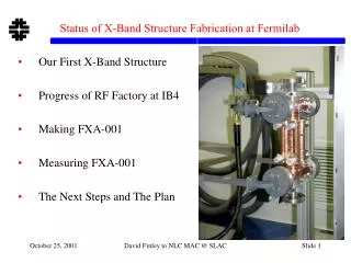
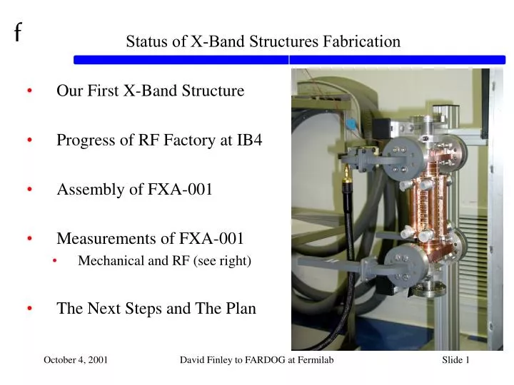
Status of X-Band Structures Fabrication • Our First X-Band Structure • Progress of RF Factory at IB4 • Assembly of FXA-001 • Measurements of FXA-001 • Mechanical and RF (see right) • The Next Steps and The Plan David Finley to FARDOG at Fermilab
We have our first X-Band structure. • It is about 20 cm long. • It is named FXA-001. • Note the cells, couplers, rf flanges, water pipes, beam tubes. • It took a little more than nine months. FXA-001 Setup for Mechanical QC at Fermilab Technical Division, 08/01/01 David Finley to FARDOG at Fermilab
RF Factory Elements(Norbert Holtkamp, David Finley) From David Finley’s Presentation at the May 31, 2000 NLC Collaboration Meeting at Fermilab • Seven Elements of the RF Factory • RF Design • Produce Copper / Machine Copper • RF Measurements & Development / Low Power • Structure and Vacuum • Mechanical Measurements of Straightness • Brazing / Bonding Facility • High Power Processing David Finley to FARDOG at Fermilab
Copper Material and Some Copper Parts(Tug Arkan, SLAC, Gregg Kobliska & Co.) Ordered enough bars for ~10K disks (~100 meters total). Parts machined in US industries. Have made both RDDS diamond turned disks, and conventional machined high gradient test disks. ETF needed ~5K disks. Eight Pack Test needs ~1K disks. NLC needs ~1M disks (for 500 GeV center of mass.) 9 copper bars ~10 feet long each. David Finley to FARDOG at Fermilab
Mechanical Measurements of RDDS Profiles(Tug Arkan, Ted Beale, Rob Riley) Measured four profiles (see below) along the tear-drop shaped iris of the rf surfaces of six RDDS disks. Zeiss machine costs ~$500K. Might (or might not) buy Zeiss machine because it is a general purpose light touch 3D coordinate measuring machine. Contours of RDDS disk # C001 taken from D. Sun et al PAC01. green: measured, blue: design, red: tolerance David Finley to FARDOG at Fermilab
Mechanical Measurements of Flatness of RDDS Disks(Tug Arkan, Ted Beale, Rob Riley) Zygo machine measures flatness well enough. Zygo machine costs ~$400K. Not going to buy Zygo machine until we know we are doing diffusion bonding rather than brazing. David Finley to FARDOG at Fermilab
Couplers, Disks, Brazing Materials for FXA-001(Tug Arkan, Gregg Kobliska & Co., Brian Smith, Danny Snee.) Some brazing materials etc. Coupler main body, partly diamond turned. Coupler and beam tube subassembly. 45 mm OD disks for high gradient tests David Finley to FARDOG at Fermilab
Sub-Assemblies at Alpha Braze (Fresno, CA)(Tug Arkan, Brian Smith, Danny Snee) Both Couplers with beam tubes. Couplers and disks. <<< Note mirror quality rf surfaces provided by diamond turning machining. Leak Check. Cooling water tubes and test blocks. David Finley to FARDOG at Fermilab
Final Assembly at Alpha Braze (Fresno, CA)(Tug Arkan, Brian Smith, Danny Snee) David Finley to FARDOG at Fermilab
NICADD Furnaces(Jerry Blazey, Steve Holmes, Tug Arkan, Gregg Kobliska & Co.) • The small furnace in place in IB4. • First use will be for bonding and brazing studies. • Then it will be used to make sub-assemblies. • Will likely also be used for electron cooling and maybe scrf. • Need full sized furnace for final assembly. David Finley to FARDOG at Fermilab
Straightness QC on FXA-001 in IB4(Tug Arkan, Ted Beale, Rob Riley) Define the z axis based on disks #1 and #20. Measure the centers of the other 18 disks relative to this axis. FXA-001 Setup for Mechanical QC at Fermilab Technical Division, 08/01/01 David Finley to FARDOG at Fermilab
Straightness QC on FXA-001 in IB4(Tug Arkan, Ted Beale, Rob Riley) David Finley to FARDOG at Fermilab
RF Measurements on FXA-001(Gennady Romanov, Ding Sun, Ivan Gonin, Timergali Khabiboulline) Bead Pull Principle • A network analyzer puts an rf wave into the structure composed of cells and couplers. Some of the wave is transmitted, some is reflected, and the reflected power measured and analyzed. • A metal “bead” (shown as “needle” in the figure) is pulled along the length of the structure and disturbs the rf wave. • The analysis yields the amplitude and phase of the wave. From PAC95 paper on DESY S-Band setup David Finley to FARDOG at Fermilab
RF Measurements on FXA-001(Gennady Romanov, Ding Sun, Ivan Gonin, Timergali Khabiboulline) • Bead pull setup in RF Factory Clean Room A. • Note network analyzer (from Beams Division), bead pull support, pulley, data on computer screen, and FXA-001. David Finley to FARDOG at Fermilab
RF Measurements on FXA-001 • Here, the bead is (barely) visible against the shadow just above the beam pipe. David Finley to FARDOG at Fermilab
RF Measurements on FXA-001 • A better view of just the bead pull apparatus with FXA-001. David Finley to FARDOG at Fermilab
RF Measurements on FXA-001 Im vs. Re part of reflected rf wave at 11.400 GHz before tuning. Note: You want 11.424 GHz; thus the cells are about 24 MHz low. • The bead is pulled through the structure at a constant speed over about 140 seconds. • Data is taken at constant time intervals. • The data taking window is about 10 msec. David Finley to FARDOG at Fermilab
RF Measurements on FXA-001 Amplitude of reflected rf wave at 11.400 GHz before tuning as a function of time. • You want this to be flat - which it isn’t. • This is the same measurement as the previous slide but it is easier to see that every third peak is smaller than the other two. David Finley to FARDOG at Fermilab
RF Measurements on FXA-001 First Tuning Step: Set analyzer at 11.410 GHz, a 10 MHz step. Before After David Finley to FARDOG at Fermilab
RF Measurements on FXA-001 2nd Tuning Step: Set analyzer at 11.422 GHz, an additional 12 MHz step. Before After David Finley to FARDOG at Fermilab
RF Measurements on FXA-001 3rd Tuning Step: Stay at 11.422 GHz, and tweak cells again. Before After (same as “After” on previous slide) David Finley to FARDOG at Fermilab
RF Measurements on FXA-001 Another Tuning Step: Stay at 11.422 GHz, and tune couplers. Before After (same as “After” on previous slide) David Finley to FARDOG at Fermilab
RF Measurements on FXA-001 Amplitude vs. time after coupler tuning at 11.422 GHz. David Finley to FARDOG at Fermilab
RF Measurements on FXA-001 • Amplitude vs. cell number at 11.422 GHz before and after tuning output coupler. • Same data as: from two slides ago … but the differences are shown more clearly in this plot. David Finley to FARDOG at Fermilab
RF Measurements on FXA-001 • Phase vs. cell number at 11.422 GHz before and after tuning output coupler. • Same data as: from two slides ago … but the differences are shown more clearly in this plot. David Finley to FARDOG at Fermilab
Summary of FXA-001(David Finley’s Observations and Tactics) • It is a learning experience (it is not junk) and it has taught us some of what we need to learn to join copper together. • But it is not an accelerating structure, and may or may not be used for “high gradient” structure tests. • Next we want to • see if we can make FXA-002 and FXA-003 “the same but better than” FXA-001, • make ~1 / month rather than ~1 / year, • make structures for high gradient testing, • make structures good enough for the NLC Main Linac, • make two girders with six structures on each girder. David Finley to FARDOG at Fermilab
The Next Steps for X-Band Structures at Fermilab(David Finley, Harry Carter et al) • Engineering Teams (Harry Carter) • FY02 Budget includes 180 FTE-days at SLAC • Present emphasis is on Technical Division effort • Note: Engineering Teams include TESLA • Make Structures for the Eight Pack Test • Note: No longer talking about ETF at Fermilab. • But still involve industry as much as possible • For example, SBIRs David Finley to FARDOG at Fermilab
Engineering Teams(Harry Carter and David Finley) Originally created to help focus on Technical Division FY02-03 goals for Linear Collider R&D. But expanded to include more and is a moving target at this time. For X-Band (NLC) • Fermilab RF Factory • Structures (Mechanical) • Structures (Electrical/RF) • Girders • Vacuum System • Cooling Water System • Specifications Development • Quality Assurance Development • 8 Pack Integration Recall: Fermilab’s Linear Collider R&D Goal: By the end of 2003, complete the R&D work leading up to CD-1. • Both TESLA and NLC • FNAL Cleaning Facility • SBIRs • Permanent Magnets • Demonstration of Remote Accelerator Operation • Siting LC’s near Fermilab • Etc etc David Finley to FARDOG at Fermilab
Structures for Eight Pack Test • Eight Pack Test at SLAC (Dave Schultz) • In Phase II, a “pack of eight klystrons” will feed • 11.424 GHz X-Band power into • a modified DLDS system and • power two girders worth of structures • with the full power and energy required by the NLC design. • The (impossible) goal is to be done by the end of FY03 • Girder A: 6 High Gradient Test Structures (FXBs) • Girder B: 6 NLC Main Linac Structures (FXCs) David Finley to FARDOG at Fermilab
The (Fermilab) Plan for X-Band Structures • In FY02 (with $1.95M) • Make FXA-002 and FXA-003 • 20 cm long, conventional machined, high gradient tests, 45 mm OD • Make FXB-001 thru 003 • 90 cm long, conventional machined, high gradient tests, 61 mm OD • Assume same coupler design we had in FY01 (aka “sparky”) • Start to order parts for FXC • Final NLC Main Linac Design >>> The Real Thing • 90 cm long, assume diamond turned, real accelerators • Note: Need FXC design (including couplers) by July 2002 • In FY03 • Make FXB-004 thru 006 (plus two extras) • Assume better coupler design than we had in FY01. • Make FXC-001 thru 006 (plus two extras) • See how many we actually have in mid to late FY03 and decide what to do in FY04 David Finley to FARDOG at Fermilab
Status of X-Band Structures Fabrication • Our First X-Band Structure • Progress of RF Factory at IB4 • Assembly of FXA-001 • Measurements of FXA-001 • Mechanical and RF (see right) • The Next Steps and The Plan David Finley to FARDOG at Fermilab