Download
1 / 26
260 likes | 285 Views
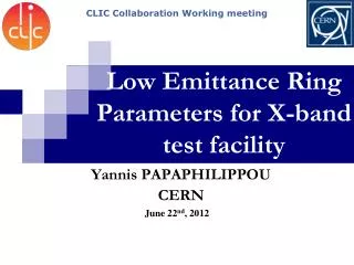
Status of KEK X-band Test Facility and its future plans. Shuji Matsumoto Accelerator Lab., KEK. Contents. The “New” X-band Test Facility (XTF) and Klystron Test Stand Ongoing High Power Test at Klystron Test Stand Ongoing X-band researches Future plans and possible collaborations.

E N D
Status of KEK X-band Test Facility and its future plans Shuji Matsumoto Accelerator Lab., KEK US High Field Gradient Collaboration Workshop, SLAC.
Contents • The “New” X-band Test Facility (XTF) and Klystron Test Stand • Ongoing High Power Test at Klystron Test Stand • Ongoing X-band researches • Future plans and possible collaborations. • Summary US High Field Gradient Collaboration Workshop, SLAC.
The “New” XTF “New” X-band Test Facility (XTF)andX-band Klystron Test Stand New XTF is under construction here. Our old place X-band Klystron Test Station Narrow Waveguide Test is ongoing here. Our new place Plan view of KEKB Injector US High Field Gradient Collaboration Workshop, SLAC.
The “New” XTF Construction of NewXTF is underway.. • The work started in Jan. 2007, moving the equipment to new place. • The operation with a single klystron will be ready at the end of July. • The operation with two klystrons is possible after the reinforcement of the wall plug power completes (Additional power line will be placed). The work will be done during our summer shutdown. • The full power (100MW) operation of New XTF will be ready in September. US High Field Gradient Collaboration Workshop, SLAC.
The “New” XTF XTF modulator and X-band ppm Klystrons C-band Exp. Area (bunker) Plan view of Acc structure assembly hall. Control Area • XTF Modulator drives two PPM X-band klystrons. • The combined power from the klystrons is guided into the experimental area (bunker). • The control/monitor station is located between the power source and the bunker. US High Field Gradient Collaboration Workshop, SLAC.
The “New” XTF XTF Modulator Control Area Bunker US High Field Gradient Collaboration Workshop, SLAC.
The “New” XTF Features of the facility • (100MW, 400ns, 50pps), 24hr/day • 50cm-thick concrete shield room (bunker) • Control system will be basically from scratch, adapting control to KEKB Injector area • Data acquisition and storage through LINUX and EPICS • RF pulse shape recording for BD and preceding pulses • Evaluation with stopping operation from the beginning • Pulse-to-pulse evaluation to be done later (dep. on money) • Phase measurement not yet planned • Dark current evaluation • Charge by FC, pulse shape with CT and energy by analyzer magnet • Acoustic measurement (developed by SLAC) • X-ray measurement with small PMT’s • Q-mass monitoring US High Field Gradient Collaboration Workshop, SLAC.
The “New” XTF Klystron LLRF CCG Data storage KEKB Inj. control Modulator INTLK Safety Mod. PLC Discri S/H & DC Amp System control PC Python, Linux X-ray TDS3034B (300MHz) TDS3054B (500MHz) RF crystal CT DL7480 (500MHz) History 4MW/ch Various signal X-ray Etc. Acc PLC Etc. VME Acoustic (SLAC) Acoustic DPO7104 (1GHz) FPGA (100MHz) Etc. Etc. AM FC New XTF control system: from the beginning, later New XTF control system US High Field Gradient Collaboration Workshop, SLAC.
The “New” XTF XTF Modulator • Line-type modulator combined withInverter charging, Thyratron switched and Pulse Transformer. Conventional design, high reliability. • The modulator installs two PFNs and thyratrons in parallel. It enables to drive two klystrons simultaneously. • The first modulator was made in 2003 in full spec, while the second one in 2004 mounts a single PFN and is “half” spec. • The first will be used for New XTF. The second runs at Klystron Test Station (in KEKB Injector) to drive a single klystron. US High Field Gradient Collaboration Workshop, SLAC.
The “New” XTF XTF Modulator (test result and operation) Klystron : 1, Inverter PS : 4, Repe. Rate : 150 Hz, Vpfn : 35 kV Pule width : 4.5 µs Flat-top width : >1.6µs(±0.5%) Rise time : 0.9µs(10-90%) Pulse voltage stability : ±0.15% • We have operated both of the modulators for past one to two years. The operation has been stable. • We have had no chance to do the two-tube operation so far. This is to be done in NEW XTF. US High Field Gradient Collaboration Workshop, SLAC.
The “New” XTF PPM X-band Klystron for XTF Operation Parameters for XTF • Operating Frequency 11.424 GHz • RF Pulse Width 0.5 µs • Peak Output Power 50 MW • Beam Voltage 460 kV • Repetition Rate 50 pps • Efficiency 43 % • The klystrons have been developed as prototypes of the GLC 75MW klystron. • 4 klystrons are alive. • 2 klystrons waiting for New XTF and • 1 klystron running at Klystron Test Stand. • We plan to rebuild 1 klystron in this FY. US High Field Gradient Collaboration Workshop, SLAC.
Contents • The “New” X-band Test Facility (XTF) and Klystron Test Stand • Ongoing High Power Test at Klystron Test Stand • Ongoing X-band researches • Future plans and possible collaborations. • Summary US High Field Gradient Collaboration Workshop, SLAC.
Ongoing Test Design of the Narrow Waveguide Type of Cu002 • To study the characteristics of different materials on high-field rf breakdown. Cu, SUS, Mo, Ti, Cr, etc. Input @100MW WR90 (the height and the width are reduced) a=22.86→14mm b=10.16→1mm VSWR 1.05 (HFSS) US High Field Gradient Collaboration Workshop, SLAC. K.Yokoyama, T.Higo, N. Kudoh
Ongoing Test Observed BD Threshold was much lower than expected. Breakdown Location and Threshold (Prototype Cu002) Locations of PMTs and acoustic sensors PMT5 Array of Acoustic Sensors Breakdowns PMT4 PMT3 PMT2 PMT1 US High Field Gradient Collaboration Workshop, SLAC. K.Yokoyama, T.Higo, N. Kudoh
Ongoing Test Test Schedule: Narrow Waveguide Klystron Test Stand with Narrow Waveguide Test Setup Apr 16: Installation started Apr 25~27: Baking May 7~: RF ON, system check May 21~: Testing of Narrow waveguides made of SUS (SUS002) Jun. ~: Testing of Narrow waveguides made of Cu (Cu004) Sep. ~: High gradient Testing is started at new XTF. ~50MW XTF Modulator PPM Klystron 5mm thick Lead Shield Box High Power Dummy Load US High Field Gradient Collaboration Workshop, SLAC. K.Yokoyama, T.Higo, N. Kudoh
Ongoing Test Narrow Waveguide: Summary • To study the characteristics of different materials (Cu, SUS, Mo, Ti, etc.) on high-field rf breakdown we designed a simplified waveguide, as the field of 200MV/m being realized at rf power of 100MW. • Prototype Cu002 had been tested at X-Band Test Facility (XTF) for about a month. We have observed rf breakdowns by bursts of x-rays, flashes of visible lights and acoustic signals. • Test of Type SUS002 has just been started at Klystron Test Stand. US High Field Gradient Collaboration Workshop, SLAC. K.Yokoyama, T.Higo, N. Kudoh
Contents • The “New” X-band Test Facility (XTF) and Klystron Test Stand • Ongoing High Power Test at Klystron Test Stand • Ongoing X-band researches • Future plans and possible collaborations. • Summary US High Field Gradient Collaboration Workshop, SLAC.
Ongoing X-band researches Yasuo Higashi Attempt on small amount of dark current and breakdown late at high gradient by removing particles and metal impurities on the cavity surface • removing particles and metal impurities techniques • - Using a semiconductor wet cleaning solution and Mega-sonic • Making thin Cu2O layer on the cavity surface • Vacuum baking at 500 deg.C • Keeping good cleanness at installation into the high gradient test setup • - Making class 100 environment • High gradient test structures • Single and 3-cell SW structure • Test data analysis • -Needs statistically analysis • - Single cell : 7 structures, 3-cell : 5 structures should be required US High Field Gradient Collaboration Workshop, SLAC.
Ongoing X-band researches Yasuo Higashi Catalogs data of Si wafer cleaning by KANTO CHEMICAL CO. Ltd.We use Frontier Cleaner W-A02 US High Field Gradient Collaboration Workshop, SLAC.
Ongoing X-band researches Yasuo Higashi 2nd Single cell SW structure preparation A-02 solution + Megasonic cleaning 960kHz, 600 W, 5 minutes operation Ultra Pure Water All parts were applied megasonic cleaning Assemble envelopment: Class 10 No vacuum leak 300 degC baking, period : 5days Still needs to improve the cleaning techniques US High Field Gradient Collaboration Workshop, SLAC.
Contents • The “New” X-band Test Facility (XTF) and Klystron Test Stand • Ongoing High Power Test at Klystron Test Stand • Ongoing X-band researches • Future plans and possible collaborations • Summary US High Field Gradient Collaboration Workshop, SLAC.
Future Plans, … Whole plan of X-band activity at KEK 2006 2007 2008 2009 2010 Design electrical and mechanical Feasibility of CLIC scheme SLAC short-cell stack Fabrication of CLIC equivalent. acc structure Trial fabrication Fabrication of actual acc structure Low power test High power test High power / high field experiment at New XTF Narrow waveguide GLC acc structure Basic structure ・・・ CLIC acc structure ・・・ CLIC equivalent, acc structure High power test at SLAC and CERN Compact accelerator fabrication and testing RF Gun for Tokyo U. 2nd 1MeV accelerator 1st 1MeV accelerator Several MeV accelerator ............. US High Field Gradient Collaboration Workshop, SLAC.
Future Plans, … X-band activities in 2007 • Discuss with SLAC and CERN on collaboration • High-field test with narrow waveguide • Cu with various surface condition • Comparison among Cu, SUS, Mo, Ti, …. • High-field test at new XTF • Firstly establishing high-power test system • Accelerator structure test • High-field tests in general • Test fabrication of CLIC structure • Acquire the experience of CLIC design • Fabrication of cavities for test at SLAC KLY lab. • Surface treatment method • Fabrication of compact accelerator • 1MeV accelerator, RF Gun, etc. US High Field Gradient Collaboration Workshop, SLAC.
Future Plans, … XTF plan in 2007 • KLY test station (50MW level) • Apr.-July: Narrow waveguide high-field test • Summer~: Continue waveguide components tests • Jan.~: Rebuilt klystron test • New XTF (100MW level) • June-July: Check two klystron operation • Aug.-Sept.: Operation with combining two klystrons • Oct.: Startup high field study system with an old GLC structure • Nov.-Dec.: High-field test of CLIC-related structure • As needed: Narrow waveguide test, single-cell test, etc. • Welcome any high power test plan US High Field Gradient Collaboration Workshop, SLAC.
Summary • X-band activity in KEK will continue at least the next few years in close relationship with KEKB Injector RF and ACC groups. • 50MW X-Band Klystron Station is running. 100MW “New XTF” (name not fixed yet) will be ready to go in summer 2007. • It is expected to have 100MW 0.4us 50pps pulses available for the high power tests at New XTF. • These X-band facilities are open to (international) collaborations. • KEK X-band group conducts basic RF breakdown experiments as well as the accelerating structure and component tests. • Development of the key devices or the components, such as a klystron, will be continued (although the budget is very tight.) US High Field Gradient Collaboration Workshop, SLAC.
KEK X-Band Group:List of the peoples participate in these researches • Mitsuo Akemoto, Shigeki Fukuda, Toshiyasu Higo, • Takuya Kamitani, Noboru Kudoh, Shuji Matsumoto, • Kazue Yokoyama, Mitsuhiro Yoshida Accelerator Laboratory, KEK Yasuo Higashi, Toshikazu Takatomi, Kenji Ueno Mechanical Engineering Center, KEK US High Field Gradient Collaboration Workshop, SLAC.