Download
1 / 35
350 likes | 574 Views
Structure of Computer Systems. Course 10 Interconnection systems. Interconnection systems. Purpose: connect different components of a computer system (CPU, memory, interfaces, peripheral devices) - buses interconnect multiple computer systems – networks why?

E N D
Structure of Computer Systems Course 10 Interconnection systems
Interconnection systems • Purpose: • connect different components of a computer system (CPU, memory, interfaces, peripheral devices) - buses • interconnect multiple computer systems – networks • why? • exchange of data and instruction codes • synchronization and coordination of actions • events signaling
Interconnection systems • Evolution • Inside of a computer system: • first 3 generation of computers – dedicated connections between computer modules • microprocessors (4th generation) – system bus • high performance processors – multiple buses with different speeds and destinations • multi-core processors – network-on-chip • Between computer systems: • first generations – dedicated point-to-point serial connections • the 80’s – network communication and Internet • last years – very high speed interconnection systems for Grids and clusters (e.g. InfiniBand)
Interconnection systems • Design decisions • general purpose or dedicated connections • serial or parallel • synchronous or asynchronous • speed • dimension/distance (in circuit, on board, on system, inter-system) • single or multi-master
Interconnection systems • Interconnection system examples • General purpose, parallel, asynchronous, single and multi-master bus (classical system bus) • General purpose, parallel, synchronous bus • Transactional parallel buses • Specialized, parallel buses • Serial, point-to-point, and multipoint asynchronous buses • Serial, synchronous buses • Peripheral serial buses
General purpose, parallel, asynchronous bus (classical bus) • purpose – one interconnection environment for all the components of a computer • features: • parallel bus – transfer is made on multiple parallel lines (signals) • asynchronous – the bus in not controlled by clock signal; signals travel on the bus with a limited speed causing delays • single master – only one module (the CPU) can initiate transfers on the bus • multi-master – multiple modules can initiate transfers on the bus
General purpose, parallel, asynchronous bus (classical bus) • signals (sub-buses): • address signals A0- An – used for specifying the location of the transfer (memory location or I/O register/port • 2n – the maximum addressing space allowed by the bus • selecting an optimal n: • too small – limit the addressing space • too big – wasted space on the board • data bus D0-Dm – used for transferring data or instruction codes • m - the maximum width of the data, which can be transferred in a bus cycle; in accordance with the CPU structure (e.g. 8, 16, 32 or 64 bits)
General purpose, parallel, asynchronous bus (classical bus) • signals (cont.) • control and command signals – used to control the traffic on the bus (examples from ISAx86) • command signals – determine the type of the transfer cycle • MRDC\ (memory read command), MWTC\, IORC\, IOWC\, INTA\ • control signals – enable and disable data and address amplifiers, validate transfers, reset the system • DEN (data enable), ALE (address latch enable), Ready, RST (reset) • interrupt signals – used for signaling events • IRQ0-IRQ7 (interrupt request) • bus arbitration signals – in multi-master buses, used for deciding who has the control of the bus • BRQ, BGT or HOLD, HOLDA • clock signals – used for synchronization or for generating other useful frequencies • CLK, BCLK (bus clock), PCLK (peripheral clock) • power signals • GND, Vcc, +12V, -12V
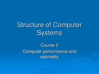
General purpose, parallel, asynchronous bus (classical bus) • a single bus configuration with: CPU(s), memory modules, Input/Output interfaces and devices CPU Memory Memory Address bus Data bus System bus Control bus I/O int. I/O int. I/O dev. I/O dev.
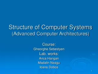
A0-An valid address MRDC MWTC Ready D0-Dm valid data taccess tcycle General purpose, parallel, asynchronous bus (classical bus) - time diagrams Memory Read Cycle
Memory Write Cycle A0-An valid address MRDC MWTC Ready D0-Dm valid data taccess tcycle General purpose, parallel, asynchronous bus (classical bus) - time diagrams
General purpose, parallel, asynchronous bus (classical bus) • Advantages: • simple operation (easy to understand and debug) • simple design of bus modules • no dimensional limitations (asynchronous mode) • single communication environment for all the components of a computer • Drawbacks: • low speed – limited to the slowest module • limited number of modules connected on the bus (10-16 – see fan-out of a TTL circuit)
General purpose, parallel, asynchronous bus (classical bus) • Examples of general purpose, parallel, asynchronous buses: • 8086 bus • ISA (Industry Standard Architecture), EISA (extended ISA) • S-100 EISA connectors and Interface board
General purpose, parallel, synchronous bus • Why ? (Purpose): increase the speed through a better control of timing • How ? (Principles) • every signal on the bus is related (synchronized) with the clock signal • modules may anticipate next steps (does not have to wait until a signal arrives to the module, as in asynchronous mode) • modules on the bus must have some intelligence • Examples: • PCI • P6 (Pentium Pro) bus
General purpose, parallel, synchronous bus • Block read cycle (PCI bus) • request for a block of data (first period) • memory generates data from consecutive addresses
General purpose, parallel, synchronous bus • Advantages: • higher transfer speed • small average access time • promotes block transfers (good for cache line transfers) • Disadvantages: • dimension of the bus is limited by the clock frequency • if the bus is too long, clock signal is not synchronized with itself at the two ends of the bus (the speed of the signal is limited) • more complex design of modules connected on the bus • harder debugging process
Transactional, parallel, synchronous buses • Why ? (Purpose): increase the speed of the bus • How ?(Principles): • pipeline implementation of a transfer on the bus • use transaction (set of operations) instead of transfer cycles • a transaction divided into stages that use different signal groups and therefore can be executed in a pipeline manner • Example: • P6 (Pentium pro) bus
Transactional, parallel, synchronous buses • Example: the P6 bus • Phases: • Arbitration– decides which master has access on the bus • Transfer request– specifies the request (read or write, start address, number of bytes) • Snooping– detect and solve cache inconsistencies • Error – detect and solve transmission errors (ECC – error correction code on data and parity on address and command signals) • Response – specifies the type of the answer (now, delayed, refused) • Transfer– data transfer in accordance with the request
Transactional, parallel, synchronous buses • P6 bus (cont.)
Specialized, parallel buses • buses specialized for a group of peripheral devices (e.g. HDD, DVD, etc.) • Examples: IDE, SCASI (read “scazi”), ATA • SCASI details: • assures communication between an initiator (computer) and a target (peripheral device) • protocol steps: • initiator sends a command (command descriptor block) to the target • target respond with a status code (success, error or busy) • target returns a Check condition and the initiator respond with SCI Request sense command • there are about 60 command types grouped in 4 categories: • non-data, read, write and bidirectional • SCASI and ATA have serial versions too
Multi-master parallel buses • Issue: • the bus is a shared resource; only one master can control the bus at a given moment • how to establish who has the control of the bus • Solutions: • centralized control • the central CPU is controlling the access on the bus – • example: DMA transfer (HOLD, HOLDA handshaking mechanism) • bus arbiter circuit • example: I8289 – bus arbiter (BRQ, BGT, CBRQ) • distributed control • every master has an arbitration component: • serial link • token bases
Serial buses • Serial bus v.s. parallel bus • less signals (lines) • longer transmission distances • cheaper implementation (e.g. less wires, less space on the PCB - printed circuit board, less pins on the circuits) • speed: • old view – lower speed than parallel connection • new view – higher speed than parallel connection • explanation - its easier to increase more than 10 times the transmission frequency on serial bus than on a parallel one (see electro-magnetic interferences in case of long parallel lines) • consequence – most of the parallel buses are replaced with serial ones: • serial ATA and SCASI • network-on-chip • serial system buses – e.g. I2C for microcontrollers
Serial buses • Design decisions: • synchronous or asynchronous • point-to-point or multipoint • character-based or message-base • information coding: voltage levels, differential voltages, light impulses, radio waves • flow control: hardware, software, protocol-based • error detection and correction
Data signal Shift reg. Shift reg. Clock signal GND Sender Receiver Clk Data 0 1 1 0 1 0 0 0 Serial buses – Synchronous transmission • synchronous – an extra clock signal controls the transmission
Serial buses – Synchronous transmission • Features • easy to implement, no other synchronization mechanisms are needed • requires an extra signal (clock), inefficient use of wires • hard to synchronize sender and receiver on long distances
Serial buses – Synchronous transmission • Example: I2C protocol (read: eye to see) • multi-point, serial, synchronous bus • used in microcontroller systems to connect external components: memory circuits, analog-digital converter • master-slave protocol (1 master controls the traffic on the bus) • uses two lines: SCL- clock and SDA - data address
Serial buses Asynchronous transmission • Features • no clock signal • synchronization made through the specific structure of the transmitted data • the sender and the transmitter must use the same protocol that specifies: • transmission frequency • number of bits/character or bytes/message • coding of logical 0 and1 • data-flow control mechanisms • error detection method
Serial buses Asynchronous transmission • best known protocol (standard): RS232 or V24 • Specifications of RS232 protocol: • point-to-point bidirectional transmission on characters • standard frequencies: 300,600, 1200 ...9600 ...Bauds • bits/character: 6,7, 8 bits • 1 START bit = 0 and 1or 2 STOP bits = 1 • error detection – optional parity bit, even or odd • flow-control protocols: • software (XON/XOFF) – with ASCII codes for starting (XON) and stopping (XOFF) the transmission • hardware – with 2 pairs of signals: RTS-CTS or DSR-DTR
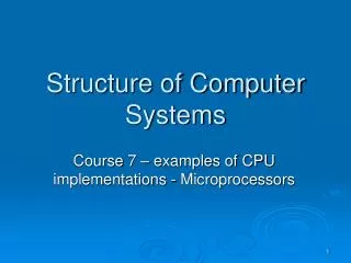
RXD TXD GND RTS CTS DSR DTR RXD TXD GND RTS CTS DSR DTR Sender Receiver Start data bits (6-8 bits) Parity Stop (1-2 bits) Serial buses – Asynchronous transmission • Specifications of RS232 protocol (cont.): • signals: • RXD – receive data • TXD – transmit data • GND – ground (voltage reference) • RTS – request to send • CTS – clear to send • DSR - data set ready • DTR – data terminal ready • max. transmission distance: 100m • data format: Start (1 bit = 1), data (6-8 bits), Parity (1 bit), Stop (1-2 bits=1)
Serial buses – Asynchronous transmission • Specifications of the RS485 protocol: • multi-point, serial, asynchronous transmission on characters • transceivers (receiver-transmitter circuit) with three-state capability • transmission on two twisted wires (A and B) • bit coding: differential voltage
Multipoint interconnections • Ring • bus • tree • matrix • hyper-cube • switch fabrics
Multipoint interconnections • Crossbar switch • multiple connections between multiple components • multi-bus access of CPUs to memory modules
Multipoint interconnections • Issues: • reduce the number of connections • reduce the number of interfaces • reduce communication delays (data latency) • reduce the number of hops (nodes) involved in a transfer • increase the bandwidth
Multipoint interconnections • Implementations: • latest Intel processors (Sand Bridge) • internal ring between cache memories • QPI – QuickPath Interconnect – connection between CPUs • InfiniBand • a switched fabric communications link used in high-performance computing and enterprise data centers • features: • high throughput, • low latency, • quality of service and failover, • scalable. • The InfiniBand architecture specification defines a connection between processor nodes and high performance I/O nodes such as storage devices. Infiniband host bus adapters and network switches are manufactured by Mellanox and Intel
Multipoint interconnections • Wishbone Bus: • an open source hardware computer bus intended to let the parts of an integrated circuit communicate with each other. • the aim is to allow the connection of differing cores to each other inside of a chip. • is used by many designs in the OpenCores project.