Download
1 / 85
940 likes | 1.2k Views
IEEE 802.11n. Clause 20. IEEE 802.11n (Clause 20). This is a technological portent resulting from the application of the most advanced telecommunication theory. 802.11n. This is a technological portent that delivers high data bit rate by making use of:

E N D
IEEE 802.11n Clause 20
IEEE 802.11n (Clause 20) • This is a technologicalportent resulting from the application of the most advanced telecommunication theory
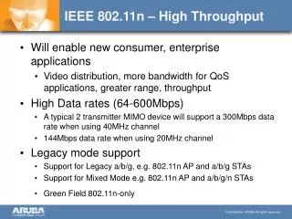
802.11n • This is a technologicalportent that delivers high data bit rate by making use of: • Multiple streams, multiple antennas • Complexdigital signal processing DSP • Orthogonal carriers in frequency division OFDM • Channel bandwidth aggregation
IEEE 802.11n Physical PHY layer
802.11n PHY Layer Summary • High Throughput (HT) PHY layer is based on the same Clause 17 OFDM PHY Layer. • However, Clause 20 (11n) adds up to four (4)spatial streams. • The operating bandwidth is 20 MHz per channel. • Additionally, 802.11n allows aggregation of twocontiguous channels to yield 40 MHz bandwidth channels. • When 802.11n operates with 40 MHz bandwidth with four spatial streams, it can reach 600 Mbps.
802.11n PHY Layer Modulators • The HT PHY data subcarriers are modulated using: • BPSK • QPSK • 16-QAM • 64-QAM
802.11n PHY Layer FEC • Forward error correction (FEC) coding (convolutional coding) with a Coding rate of: • ½ • 2/3 • ¾ • 5/6
802.11n • Other optional features at both transmit and receive sides are: • 400 ns short guard interval (GI) • Transmit beamforming • HT- greenfield format • STBC.
802.11n PHY Layer Formats • 802.11n has the following PHY layer compatibility formats: • Non-HT format: • Structured according to the Clause 17 (OFDM) or Clause 19 (ERP) specification. • Support for non-HT format is mandatory. • HT-mixed format (HT_MF): • Contains a preamble compatible with Clause 17 and Clause 19 receivers. • The rest of the frame cannot be decoded by Clause 17 or Clause 19 STAs. • Support for HT-mixed format is mandatory. • HT-greenfield format (HT_GF): • Frames of this format assume only Clause 20 devices operate in the BSS. • Support for HT-greenfield format is optional.
802.11n PHY Layer HT Preamble • The HT-mixed format ensures compatibility with non-HT devices by using fields that the non-HT devices can read. • The HT-greenfield format does not have any field that could be read by non-HT devices.
Making use of The phase difference
Multipath Effect • Wireless station STA transmits RF waves which are received by the wireless access point WAP • Both antennas Left and Right pick up the signals
Multipath Effect • The antennas are separated by certain distance • Typically, the wavelength size • Suppose that the STA is separated from the left antenna by a distance of 1.2 metres and that the wavelength is 0.12 metres (for 2.4 GHz Band) • What is the distance to the right antenna?
Multipath Effect • What is the distance to the right antenna? • The difference between the left and right distances is merely 0.0059 metres (5.9 mm) • However, the WAP is designed to perceive such slight difference by detecting the phase difference • The WAP can detect which of the two path is the shortest • Consequently, the WAP can choose the strongest and most direct signal path
Multipath Effect • The WAP can detect the position of the client depending of the combination of phases that appear in the two antennas
Extending this Concept • Multipath has been a traditional problem for wireless communications. • However, by implementing a very clever disposition of antennas, and signal processors, multipath can become an ally.
IEEE 802.11n MIMO
Spatial Multiplexing • Spatial Multiplexing is a wireless technology based on the separation of the main data stream into several, separate streams. • Each separate mini-stream is transmitted by a separated antenna. • However, all the separated mini-stream are modulated in the same frequency channel. • In the receiving side, all the mini-streams are reassembled together using a special signal processing technology (MIMO).
MIMO Principles • The idea of MIMO is actually very old. • But it was difficult to implement because it required very precise phase locking technologies. • Nowadays, this is easier to implement with modern electronics digital processors and phase locking integrated circuits.
For Example • A radio link is designed so that two streams are transmitted to a destination with two receiving antennas. • The two streams carry different information however their carrier frequency is the same. • Problem: • How to accomplish this setting without interference? • How to recover each information stream at the receiving site?
For Example • Frequency = 300 MHz • Lambda = 1 m • Distance D = 100 metres • Hypotenuse = 100 metres plus ¼ lambda • What is height h2?
MIMO • Frequency = 300 MHz • Lambda = 1 m • Distance D = 100 metres • Hypotenuse = 100 metres plus ¼ lambda • What is height h2? Or where to place the bottom antenna so that the previous condition happens.
Pythagoras • Frequency = 300 MHz • Lambda = 1 m • Distance D = 100 metres • Hypotenuse = 100 metres plus ¼ lambda • What is height h?
Pythagoras • Distance D = 100 metres • Hypotenuse = 100.25 metres • What is height h? • Height is 7.07 metres
Two TXs, Two RXs • Now, let’s add a second transmitter B with the same separation of 7 metres and the same wavelength as before. • Receiver RXA gets the signals from both TXA and TXB . • Receiver RXB gets the same signals than RXA
Two TXs, Two RXs • Let’s call: • The signal transmitted from TXA lambda A (ƛA) and... • The signal transmitted from TXB lambda B (ƛB) • Both Receivers RXA and RXB get the signals transmitted from SITE A.
Two TXs, Two RXs • All together: • Receiver RXA gets ƛAand ƛB delayed ¼ ƛB at the same time. • Receiver RXB gets ƛB and ƛA delayed ¼ ƛAat the same time.
RXA ƛA ƛB delayed ¼ ƛB • Receiver RXA gets ƛAand ƛB delayed ¼ ƛB at the same time. ¼ wave
RXB • Receiver RXB gets ƛBand ƛA delayed ¼ ƛA at the same time. ƛA delayed ¼ ƛA ƛB ¼ wave
Two TXs, Two RXs ƛA ƛB delayed ¼ ƛB • Let’s take the received signals at Receiver RXA • That is ƛAand ƛB delayed by ¼ ƛB combined. ¼ wave
Two TXs, Two RXs • Let’s place a device, in series, that further delays the signals by ¼ wavelength.
The Effect of a new delay • Let’s place a device that delays the signals by another ¼ wavelength. • This happens: Reference Line ƛB delayed ¼ ƛB ƛA Input Signals After the added delay (see how the signals have shifted to the right with respect the input signals above) ½ wave
Delay Effect • The signals are delayed ¼ of a wave again causing: • A to become a negative cosine and • B to become a negative sine Additional Delay of ¼ wave
All together • Now, let’s add the output of the delay device to the signals present in RXB • What is the result?
Adding the Signals • This is the result of received signals at RXA after being delayed again by ¼ wavelength • What is the result? - cosine + sine - sine • These are the signals as they are received at RXB - cosine • This is exactly the desired effect. • The antenna RXA receives the • two signals but only one is • obtained at the end of the • process. • Even better, the signal is doubled • in amplitude. • This is the result of adding the previous signals: • The + sine cancels out with the – sine. • The two – cosine signals add up to have a stronger signal
The Complete Scheme • What is the point of all this complication?
The Complete Scheme • What is the point of all this complication? • The point is that both “sources of information A and B” can be transmitted using the same licensed carrier frequency. • Just one carrier frequency for two different radio links. • The signals interfere with each other in the air, but it does not matter, because they are recovered at the destination by this ingenuous system.
The Complete Scheme • This is the fundamental principle of “spatial multiplexing” • A type of spatial mux are MIMO radios or Multiple Inputs Multiple Outputs radios. • It is a more efficient way to use the radio spectrum. • However, do not see this technology as a “license to print money” as there are practical limitations like in any other technology.
Just to be clear • The previous example used a difference of phase of ¼ wavelength between signal A and B because it is easier to demonstrate. • By no means, it is required that the difference of phase be ¼ wavelength. • In principle, any phase difference, that can be detected, could be used. • This is where the Digital Signal Processor DSP has a central role. • As long as the DSP can detect the phase differences, it will process the received signals accordingly.
Implementation in IEEE 802.11n SPATIAL multiplexing
Spatial Multiplexing • Spatial Multiplexing is a wireless technology based on the separation of the main data stream into several, separate streams. • Each separate mini-stream is transmitted by a separated antenna. • However, all the separated mini-stream are modulated in the same frequency channel. • In the receiving side, all the mini-streams are reassembled together using a special signal processing technology (MIMO).
Spatial Multiplexing • The main data bit stream is separated into several streams • Each separate mini-stream is transmitted by a separated antenna • All the separated mini-streams are modulated in the same frequency channel
Spatial Multiplexing • The problem is: how does the receiving-end differentiate and detect the several streams and put the data back together?
Spatial Multiplexing • Multipath signals are actually used to recover the data stream
Spatial Multiplexing • A MIMO (multiple input multiple output) digital signal processor recovers and reassembles the data
Spatial Multiplexing • A processor extracts the desired signals by performing math operations • (S1+S2)+(S1-S2)=2S1 • (S1+S2)-(S1-S2)=2S2
Spatial Multiplexing • 802.11n defines Multiple Input Multiple Output in configurations of MxN:S • M is the number of transmitters • N is the number of antennas • S is the number of spatial streams • For example, 3x3:2 means 3 transmitters, 3 antennas and 2 spatial streams
IEEE 802.11n Channel utilization