Download
1 / 35
360 likes | 598 Views
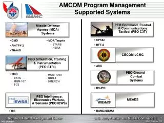
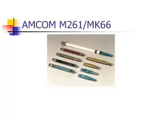
AMCOM Mk66 Project. Adrian Lauf Filiz Genca Ashley Devoto Jason Newquist Matthew Galante Jeffrey Kohlhoff Shannon Stonemetz. What we have. Program source code/operating system (core) Interface specification identifications Processing core. RMS procedural outline.

E N D
AMCOM Mk66 Project Adrian Lauf Filiz Genca Ashley Devoto Jason Newquist Matthew Galante Jeffrey Kohlhoff Shannon Stonemetz
What we have • Program source code/operating system (core) • Interface specification identifications • Processing core
RMS procedural outline • Inform missile of ready state • Feed missile coordinates of target and position • Send fire go signal • Receive error control signals via serial • End
Rocket management system • Current system uses analog line for purposes of charging a timing capacitor • Proposed implementation of an RS-232 digital serial interface • RS-232 allows for target data transfer at comfortable data rates, from 300bps to 115200bps. • Standard 9600bps baud rate will more than likely suffice
Rocket management system (cont’d) • RS-232 implementation at 12V active-low • Allows for extended serial cable lengths • Allows for debugging based on a PC serial port using 12V active-low • PC may be used in conjunction with Matlab, C or other to simulate rocket management system outputs • Data format based on target data: • Current position and elevation • Target position and elevation • Current speed • Guidance module returns “target acquired” signal
IMU • IMUs may provide analog or digital outputs; IMUs that we have researched mostly output serial digital signals • 2-wire serial outputs, 5V TTL to Altera serial I/O line • Standard to be defined
IMU • Selected system: Honeywell GunHard MEMS IMU • Serial I/O • 5VDC power supply • 9600bps data transfer rate • Requires 422 to 232 conversion
GPS • G12-HDMA receiver • 4.25’’ tall x 2.3’’ wide • Weight – 0.175 lb • Power – 1.8 W receiver 0.3 W antenna • Max Acceleration – 23 Gs up to 30 Gs • Initialization time – 45 sec cold and 11 sec hot • Time-To-First-Fix – 3 sec • Reacquisition – 2 sec • Operating Temperature - (-30) C to 70C
GPS • Digital serial I/O lines • 5VDC (TTL-level power), no voltage division required • Data transmission rate at 9600bps will allow for more than 8 times the necessary data rate for 16 corrections/sec
Datamap ser. GPS RMS 3 3 RS232 Actuator Control Cyclone ser. 4 ADC 3 IMU Feedback n 8 par. SDRAM PC100
How we will simulate • RMS, GPS and IMU data will be provided (simulated) by a PC • All I/O will take place through one RS-232 port
To be done • Physics modeling • I/O polling routines • System software compilation and loading • Bus/Battery power transition
ME Timeline Canard Deployment System Construction Design Finalization One Month Two Months Present Outer Shell Construction Simulation and Amcom Presentation
Outer Shell ConstructionCurrent Configuration • Splined connection on warhead-receiving end • Intended to align pin connection on module with warhead • Warhead secured by bolts • Axial forces concentrated on • bolts • Difficulty in machining
Outer Shell ConstructionCurrent Configuration • Threaded interface on motor-receiving end • Threads matched to rocket motor • No construction/machining operation defined • Substantial warhead modification required
Outer Shell ConstructionProposed Configuration • Press-fit interfaces for both ends of avionics module: • Ease of construction • Greater area of • material for force • distribution • 15in length
Outer Shell ConstructionProposed Configuration • Male threaded interface: • 2.3895in OD • 6 threads/in pitch • .5in press-fit shank • 1.5in threaded end • 7/32in wall thickness • Shoulder machined for positive stop
Outer Shell ConstructionProposed Configuration • Female threaded interface: • 2.625 OD • 7/32in wall thickness • ID machined to match size/pitch of war head • .5in press-fit shank • Shoulder machined for positive stop
Press-Fit Interfaces Joint StrengthBackground • Fμ = μFN = μpA = μpπdl • FN : normal force • μ : coefficient of static friction • p : contact pressure • A : area of surface contact • d : joint diameter • l : joint length
Press-Fit Interfaces Joint StrengthDesign Considerations • Design for worst case scenario: • Max. Weight : 34.4 lbs • Max. G’s : 80 @ .965 seconds • Max Jerk: 957,303 ft/s^3 @ .01 seconds • Material: • Aluminum 3356-T06 Alloy
Press-Fit Interfaces Joint StrengthDesign Considerations: Graphs
Press-Fit Interfaces Joint StrengthDesign Considerations: Graphs
Press-Fit Interfaces Joint StrengthCalculations μ = 1.35 m = 34.4 lbs. gmax = 80 Fμ = μFN mgmax = μFN FN = 65,640 Slugs • l = .5in • d = 2.3895in • P = 17.5 kpsi Yield Strength:43.5 kpsi Mod. Of Elasticity:53.7 kpsi
Press-Fit Interfaces Joint StrengthTesting • Simulation • ETB (Engineer’s Toolbox) Interface • Fit Software • Tensile Testing Machine • Load to failure
Canard Configuration • Due to poor supersonic behavior, flat plate canards are unacceptable • Will use a NACA four digit series symmetric airfoil to accommodate supersonic portion of mission • NACA 0012 with a chord length of 1.25in • Force analysis from last year determined TI-6A1-4V alloy is the desired canard material
Canard Characteristics Con’d • total length- 3.4375 in • external length- 3 in • individual mass- .031 lb • total mass- .123 lb • NACA 0012 cross section • chord length- 1.25 in
Canard Deployment • Current design has canards opening towards front of missile • Deployment forces required are too high to implement • Proposed design takes existing internal setup and rotates 180 deg • Canards open towards rear of missile Front
Deployment Forces • 12 lb force needed to deploy canards in current design due to g-force • Aerodynamic force not included in calculation. • This is not feasible • These forces aid in deployment when canards open towards missile rear
Canard Actuation • Considered use of gearbox with the servo motors to actuate canards • Gear boxes are compact and provide reductions • Some gear boxes prevent motor back drive • However, due to limited space, gear boxes are too large to implement
Canard Actuation • Decided to use actuation mechanism designed previously • Spatially will meet requirements • Drive system always engaged • Allows for addition of damping system • Further development required • Gear system • Damping mechanism • Deployment mechanism
Missile Simulation • Utilizing Matlab’s Aerospace Blockset to simulate mission • Building on the simulation from last year. • 6 dof, determine forces on airframe, determine required guidance forces • Current Improvements • Determine missile orientation upon deployment, determine fin actuation needed to produce guidance forces, model airfoil shape in simulation
References • Pictures: Tensile Testing http://www.instron.us/wa/products/universal_material/3300/default.aspx • Press-fit Calculations • http://facta.junis.ni.ac.yu/facta/me/me2001/me2001-15.pdf • AMCOM