Download
1 / 14
140 likes | 279 Views
AMCOM MK66 Guidance Module. 3-29-2005. Servo Driving. 20mA, 5V line (low current/low voltage line) Need to drive servo of 12V and 500mA to over 1A (high current line/medium voltage)

E N D
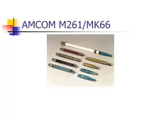
AMCOM MK66 Guidance Module 3-29-2005
Servo Driving • 20mA, 5V line (low current/low voltage line) • Need to drive servo of 12V and 500mA to over 1A (high current line/medium voltage) • Discussed possibility of using transformers, op-amps, step-up converter, other specific servo drive systems, etc. • ADP3000 – step-up/step-down switching regulator • National Semiconductor - LM2577 – simple switcher step-up regulator (ability to customize)
Servo Line Signals • Send high-level output to line driving device • Once servo deflection occurs, stop while line voltage still high, return to neutral when line voltage low • One line each for positive and negative deflection • Drive Voltage = (Circuit V) AND (Sensor V)’
SimulationPhase 1 RS232 Navionic input simulation FPGA simulator (program runs here)
SimulationPhase 2 RS232 Navionic input simulation FPGA runs flight software
Simulation types • Fixed-frame • All inputs predetermined • System follows path, all error conditions known • Dynamic-frame • Inputs modified during trial run • e.g. addition of crosswinds • Path can be set to randomly modify
IMU • Accel. position translation routine in progress • Meeting established w/Dr. Milostan 3-30-2005 • Completion date 3-31-2005 • Integration into simulation by April 05 2005
Construction • Female Interface: Previous: New:
More Construction • Male Interface:
More More Construction • Outer Shell: • 3.809” (nominal 3.75”) to 3.76” OD • Wall thickness 7/32” to 1/16” • Lathe utilized
Construction To Do List: • Cut stub acme threads (internal and external) for both female and male, respectively • Professionally machined due to lack of tool and time • Finishing Touches using Mill and Lathe
To Do: • Finalizing design on actuation mechanism • Ordering planetary gear • Finishing construction on interfaces and outer shell