Download
1 / 19
250 likes | 638 Views
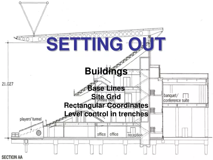
SETTING OUT. Buildings Base Lines Site Grid Rectangular Coordinates Level control in trenches. Baselines. Baselines may be described as a straight line whose terminal are fixed in relation to some other detail. Baselines are found in a variety of forms. Building Line:

E N D
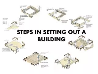
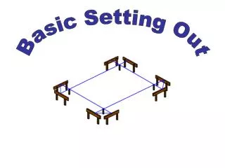
SETTING OUT Buildings Base Lines Site Grid Rectangular Coordinates Level control in trenches
Baselines • Baselines may be described as a straight line whose terminal are fixed in relation to some other detail. Baselines are found in a variety of forms. • Building Line: • A building line is defined as a line laid down by a local authority, usually a distance from a nearby road, over which no part of the building may encroach
Baselines • Site centreline: • This type of baseline is encountered on industrial type complexes such as sewage works where the distances between various plants are defined in relation to each other. • Road centreline • A road centreline comprises a series of straight lines connected by horizontal curves. These straights can become the baselines for setting out buildings.
Baselines • Coordinated Baseline: • This type of baseline can be found on an increasing number of sites. It is defined from the Primary setting out network. Rectangular coordinates define the terminals and are set out from coordinated control points. The baseline must be checked for length both by calculation and site measurement. The WCB of the baseline can also be checked against its computed value.
Location of building from a Baseline • Once baseline has been set out and checked the building can be located by the use of rectangular offsets: • Locate pegs along baseline from where the offsets are to be measured. • Distances measured as a series of RUNNING MEASUREMENTS and then individual peg distances checked. • Difficult to do over long distances or sloping ground with a steel tape but use of Total Station makes this easier and possibly more accurate.
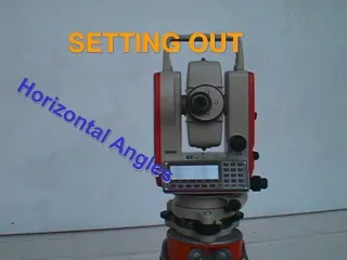
Location of building from a Baseline • Theodolite should be used for the determination of right angles. • Squareness to be checked for by comparing diagonals with calculated value.
Location of building from a Baseline • An alternative approach is to set out the first line of the building and then this line checked. The remainder of the building is then set out from this tertiary baseline. This approach allows corrections to be made immediately, if found to be necessary. Check diagonal before proceeding with next corner Step 1 Step 2
Irregular shaped buildings • Turn into rectangle if possible Accumulative errors are prevented because they fit in between fixed points
SITE GRID • A site grid is a system of lines set out parallel and square to each other and a set distance apart. • Grids can be set out several ways depending on the nature and complexity of the site: • By Setting out from a coordinated baseline with offsets. • By Intersection from the terminals of the base., but does require the use of two theodolites. • By calculating the coordinates of all grid intersections and setting out from site Primary controls.
(a) (b)
SITE GRID • In all the above methods the following checks should be made: • Each grid side should be checked for length • Each grid diagonals should be compared to calculated value. • All pegs along a particular grid line should fall on the same line – check with a theodolite.
Location of Buildings from a Site Grid • Each grid line now becomes a separate base line and the building corners can be set out by rectangular offsets as previously described. Once again the building corners must be checked for accuracy and squareness.
Rectangular Coordinates • The location of building corners by rectangular corners has been dealt with in setting out using radials. • Primary control points as reference stations should be used if possible • Again the distances between corner pegs must be checked and corrected if necessary.
Control of Line and level • Once the corner pegs have been located offset reference pegs or Profile boards need to be located as the corner pegs will be lost once excavation commences. • Offset Pegs need to be put in at a standard offset (2m – 3m) and have been fully described in the section on drainage. • Relocation of the corner pegs may be completed by stringlines between offset reference pegs. • A plumb line dropped from the stringline intersection will locate the corner peg in an excavation.
Locating peg at bottom of excavation Alternately Theodolites or total stations could be used to relocate the bottom corner pegs. (Easier to locate far corner)
Profile Boards • The use of Profile Boards for referencing a building is a far superior method to the use of offset pegs. • Building Lines are produced on to the boards where they are marked either by a saw cut or a nail. • Profile Boards should be as close to the ground as possible. • Should all be set to the same level if possible and relative to FFL (Finished Floor Level) • The boards must be set Parallel to the building lines and a reasonable distance from them to allow access for plant.
Controlling Level of Trench Bottom • The depth of foundation trench will be fixed by design. • Sight rails or profile boards are used. • A traveller length is determined bearing in mind the depth of trench and the height of the rails above ground level. • Excavation is controlled in the usual way.
Control of Concrete Levels • Control of level of traditional strip foundation is by steel level pins knocked in to concrete top level along th etrench bottom. • Concrete is then poured to the top of the pins. • With trench fill, level control is by pegs knocked into the side of the trench at concrete level.