Download
1 / 1
10 likes | 169 Views
Preparation for Troubleshooting : A labeled schematic with proper dc and signal voltages. You should know the expected voltages in the circuit should be before you can identify an incorrect voltage The Complete Troubleshooting Process :

E N D
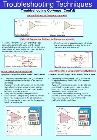
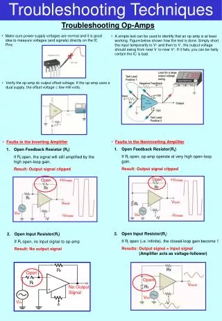
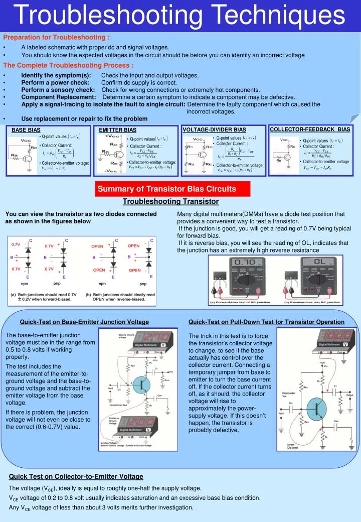
Preparation for Troubleshooting : • A labeled schematic with proper dc and signal voltages. • You should know the expected voltages in the circuit should be before you can identify an incorrect voltage • The Complete Troubleshooting Process : • Identify the symptom(s): Check the input and output voltages. • Perform a power check: Confirm dc supply is correct. • Perform a sensory check: Check for wrong connections or extremely hot components. • Component Replacement: Determine a certain symptom to indicate a component may be defective. • Apply a signal-tracing to isolate the fault to single circuit: Determine the faulty component which caused the • incorrect voltages. • Use replacement or repair to fix the problem COLLECTOR-FEEDBACK BIAS VOLTAGE-DIVIDER BIAS BASE BIAS EMITTER BIAS • Q-point values • Collector Current: • Collector-to-emitter voltage: • Q-point values • Collector Current : • Collector-to-emitter voltage: • Q-point values • Collector Current : • Collector-to-emitter voltage: • Q-point values • Collector Current : • Collector-to-emitter voltage : Troubleshooting Techniques Summary of Transistor Bias Circuits Troubleshooting Transistor You can view the transistor as two diodes connected as shown in the figures below Many digital multimeters(DMMs) have a diode test position that provides a convenient way to test a transistor. If the junction is good, you will get a reading of 0.7V being typical for forward bias. If it is reverse bias, you will see the reading of OL, indicates that the junction has an extremely high reverse resistance Quick-Test on Base-Emitter Junction Voltage Quick-Test on Pull-Down Test for Transistor Operation The base-to-emitter junction voltage must be in the range from 0.5 to 0.8 volts if working properly. The test includes the measurement of the emitter-to-ground voltage and the base-to-ground voltage and subtract the emitter voltage from the base voltage. If there is problem, the junction voltage will not even be close to the correct (0.6-0.7V) value. The trick in this test is to force the transistor’s collector voltage to change, to see if the base actually has control over the collector current. Connecting a temporary jumper from base to emitter to turn the base current off. If the collector current turns off, as it should, the collector voltage will rise to approximately the power-supply voltage. If this doesn’t happen, the transistor is probably defective. Quick Test on Collector-to-Emitter Voltage The voltage (VCE), ideally is equal to roughly one-half the supply voltage. VCE voltage of 0.2 to 0.8 volt usually indicates saturation and an excessive base bias condition. Any VCE voltage of less than about 3 volts merits further investigation.