Download
1 / 35
350 likes | 557 Views
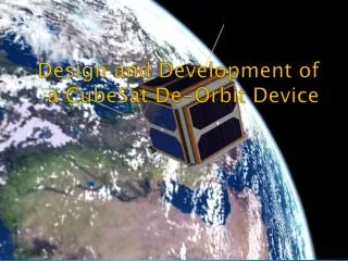
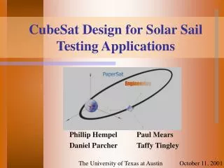
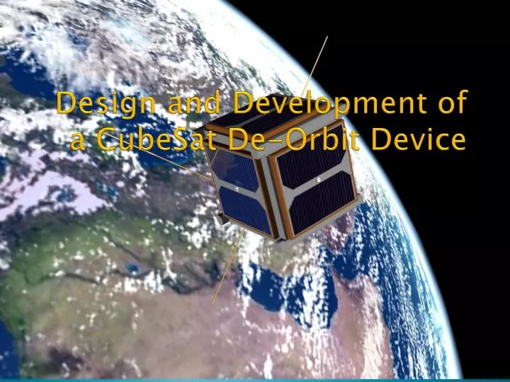
Design and Development of a CubeSat De-Orbit Device. Team Members. An Kim Cian Branco David Warner Edwin Billips Langston Lewis Mackenzie Webb Alexander Streit (ECE) Benjamin Cawrse (CS) Jason Harris (TCC). Introduction.

E N D
Team Members • An Kim • CianBranco • David Warner • Edwin Billips • Langston Lewis • Mackenzie Webb • Alexander Streit (ECE) • Benjamin Cawrse (CS) • Jason Harris (TCC)
Introduction • Thousands of man made objects in earth orbit (mostly junk). • Debris can be a serious hazard to satellites. • A paint flake caused significant damage to the Space Shuttle; it had a relative velocity between 2-8 km/s
Introduction • CubeSats are picosatellitescommonly used by universities and institutions for research in space. • Pending international treaty will require future launch stages and LEO satellites to deorbitwithin 25 years of mission completion. • Objective: design and test a de-orbit system to de-orbit CubeSats within 25 years of mission completion.
Objectives • Demonstrate commercial viability • Prove it is a robust and viable system • Achieve these objectives with a minimum cost • Orbital demonstrator • Suborbital flight • High altitude balloon flight
Objectives • Demonstrate commercial viability • Prove it is a robust and viable system • Achieve these objectives with a minimum cost • Orbital demonstrator • Suborbital flight • High altitude balloon flight
Objectives • Demonstrate commercial viability • Prove it is a robust and viable system • Achieve these objectives with a minimum cost • Orbital demonstrator • Suborbital flight • High altitude balloon flight
Objectives • Demonstrate commercial viability • Prove it is a robust and viable system • Achieve these objectives with a minimum cost • Orbital demonstrator • Suborbital flight • High altitude balloon flight
RockSat-X Program • The RockSat-X program out of Wallops Flight Facility is currently considered the best option for our test flight • RockSat-X utilizes the Terrier-Improved Malemute suborbital sounding rocket • The sounding rocket will reach apogee at approximately 160 km altitude from the Earth.
Advantages of RockSat-X • 300 seconds of microgravity flight • Power and telemetry on deck provided for timing devices, communication between ground and payload, and data storage • Direct access to orbital space after second stage burn-out when the skin of the sounding rocket is ejected. • Adequate space and weight capacity available to mount the deployment device and necessary telemetry for our test flight article
High Altitude Student Platform • 124,000 ft. High Altitude Balloon testing platform ruled out because it does not provide enough of the necessary conditions of space to adequately validate the performance of our aerodynamic brake.
Electronics Langston Lewis, Jason Harris
Review of Goals • To determine specific components suitable for our communication and sensory needs. • Configure components into useful power & telemetry system. • Show ability to retrieve data crucial for performance analysis.
Current Plan 1.22 m Dia. Telemetry & Pictures Launch & Release Commands
Status Update Package containing a majority of components was lost in mail and needs to be reorder Remaining components have been ordered and are on the way Collected sample code for major components
Coding • Sample code for camera, including transfer of picture to sd card. http://www.linksprite.com/upload/file/1286079786.txt
Coding (con’t) • Sample code for Xbee. This code sends sleep command to one Xbee https://code.google.com/p/xbee-arduino/source/browse/#svn/trunk/examples
Future goals • Having components configured properly • Have project specific code completed for the platform • Determine proper camera placement on the CubeSat
Review of Goals • To determine specific components suitable for our communication and sensory needs. • Configure components into useful power & telemetry system. • Show ability to retrieve data crucial for performance analysis.
Aerodynamic Brake Team An Kim CianBranco Mackenzie Webb
Objectives • Main objective • Develop a de-orbiting device to successfully bring down a satellite • Constraint • Small and light weight • Within low or reasonable budget • Must fit within 9x9x1 cm space
Testing Environment • The Rock Sat X flight program apogee point is 160 km • Ideal altitude is 90 km where benzoic acid sublimation is 8.35*C
Conclusion • Under ambient temperature at 90 km, there was not enough latent heat from the aluminum housing to sublimate the benzoic acid. • Air was still within the balloon producing faulty data • A heating element is required
Future Work • Fix the 18’’ diameter vacuum chamber • Have a better solution to remove air from larger Mylar balloons • Incorporate heating elements with benzoic acid tests • Verify 1.39 grams of benzoic acid will fully inflate the Mylar balloon.
O-POD Design David Warner Cian Branco
ODU Picosatellite Orbital Deployer Bolted to Rocksat-X deck, “piggybacks” rocket Stores, imparts ejection velocity to CubeSat 1.6 m/s from spring, lateral to deck Al-7075-T651 frame 1.477 kg total mass Recoverable
PATRAN FEA Analysis ongoing Vibrations @ 144Hz, inertial loading @ 25 gees, centering within 2” Quick Release Mechanism (QRM) Options Vectran Line Cutter (ODU built) 2 Linear Solenoids Improved mockup → velocity-spring experiment Newer aluminum mockup eases friction on rails Manual pin release until QRM finalized Current Work
PATRAN → Stress, Displac. Max. Deflection: .972mm Max. Stress: 55.7 Mpa Yield Strength: 507 Mpa
PATRAN → Vibration Analysis Mode 6: okay Mode 7,8(,9): problematic Mode 10: >144Hz (outside range)
Refining PATRAN model Expect at least 2 more designs of PATRAN model Improved Mesh QRM, spring on model Quick Release Mechanism design Purchase components, interface with timers Either QRM option is suitable & inexpensive CubeSat Mockup Machined version Future Work