Download
1 / 6
60 likes | 198 Views
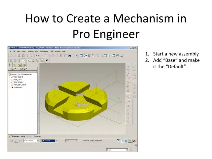
How to Create a Mechanism in Pro Engineer. Start a new assembly Add “Base” and make it the “Default”. Add Component: Slider Constraint: Make the plane through the center of the slider lined up with the plane in the dovetail slot.

E N D
How to Create a Mechanism in Pro Engineer Start a new assembly Add “Base” and make it the “Default”
Add Component: Slider Constraint: Make the plane through the center of the slider lined up with the plane in the dovetail slot. Constraint: Make the bottom surface of the slider aligned with the bottom surface of the dovetail slot. Add the second slider in the same way as the first. Add the part you created that will attach to the sliders. Constraint: Select “Pin” from the bottom left pull up menu and click on the hole cylinder and the slider peg. Constraint: Select the under side surface of the part you made and the top surface of the slider (this is the translational surface)You have attached the object to one slider at this point.
Click “placement” and “new set” Attach the other hole to the peg by pulling up the bottom left menu and selecting “cylinder” this time. Select the hole cylinder and the peg cylinder. Let’s add a servo motor to the assembly!
Pull down the Applications menu and select Mechanism. Click “Define Servo Motors:” On your drawing, click the “connection axis between the slider and the part you made.
A menu will pop up. Under Specs, select “velocity”. Under Magnitude in the “A” blank, type 30 and apply. Click “Define Analysis”. Click “Run” and “OK”
Click “replay previously run analysis” Play and watch. When you are completely finished with the assembly and mechanism features, press “Capture”. Save to desired folder to show to class. 20. “play current result set”