Download
1 / 18
180 likes | 181 Views
Learn about the fundamentals of amplifiers, including different types of circuit components, diodes, bipolar transistors, and field-effect transistors.

E N D
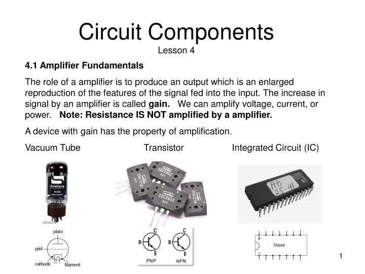
Circuit ComponentsLesson 4 4.1 Amplifier Fundamentals The role of a amplifier is to produce an output which is an enlarged reproduction of the features of the signal fed into the input. The increase in signal by an amplifier is called gain. We can amplify voltage, current, or power. Note:Resistance IS NOT amplified by a amplifier. A device with gain has the property of amplification. Vacuum Tube Transistor Integrated Circuit (IC)
Circuit ComponentsLesson 4 4.1 Amplifier Fundamentals Audio frequency or AF amplifiers are used to amplify AC signals in the audio frequency spectrum, from about 20 Hz to 20 kHz. To increase the level of very weak signals from a microphone you would use a audio (AF) amplifier.
Circuit ComponentsLesson 4 4.1 Amplifier Fundamentals Radio frequency or RF amplifiers are used for signals above 20 kHz. You will encounter both types of amplifiers when you deal with receivers and transmitters. To increase the level of very weak radio signals from an antenna, you would use a RF amplifier
Circuit ComponentsLesson 4 4.2 Diode Fundamentals The electrodes of a semiconductor diode are known as anode and cathode. In a semiconductor diode, electrons flow from cathode to anode. In order for a diode to conduct, it bust be forward-biased.
Circuit ComponentsLesson 4 4.2 Diode Fundamentals If alternating current is applied to the anode of a diode, at the cathode of the diode you would expect to see pulsating direct current. The action of changing alternating current (AC) to direct current (DC) is called rectification.
Circuit ComponentsLesson 4 4.2 Diode Fundamentals Zener diodes are used to maintain a fixed voltage. They are designed to 'breakdown' in a reliable and non-destructive way so that they can be used in reverse to maintain a fixed voltage across their terminals. The diagram shows how they are connected, with a resistor in series to limit the current.
Circuit ComponentsLesson 4 4.2 Diode Fundamentals One important application for diodes is recovering information from transmitted signals. This is referred to as demodulation. The AM detector or demodulator includes a capacitor at the output. Its purpose is to remove any radio frequency components of the signal at the output.
Circuit ComponentsLesson 4 4.2 Diode Fundamentals Light Emitting Diodes (LEDs) are solid-state semiconductor devices that convert electrical energy directly into light. LED "cold" generation of light leads to high efficacy because most of the energy radiates within the visible spectrum. Because LEDs are the solid-state devices, they can be extremely small and durable; they also provide longer lamp life than other sources. LEDs are made of various semiconducting compounds, depending on the desired colour output. Infrared and red LEDs generally use a gallium, aluminum, and arsenide compound. Orange and yellow LEDs most often use gallium, aluminum, and either indium or phosphorus. Green and blue LEDs typically use either silicon and carbon, or gallium and nitrogen.
Circuit ComponentsLesson 4 4.3 Bipolar Transistor Fundamentals The basic semiconductor amplifying device is the transistor A Bipolar Transistor essentially consists of a pair of PN Junction Diodes that are joined back-to-back. This forms a sort of a sandwich where one kind of semiconductor is placed in between two others. There are therefore two kinds of Bipolar sandwich, the NPN and PNP varieties. The three layers of the sandwich are conventionally called the Collector, Base, and Emitter.
Circuit ComponentsLesson 4 4.3 Bipolar Transistor Fundamentals In a bipolar transistor the base compares closest to the control grid of a triode vacuum tube In a bipolar transistor the collector compares closest to the plate of a triode vacuum tube In a bipolar transistor the emitter compares closest to the cathode of a triode vacuum tube
Circuit ComponentsLesson 4 4.3 Bipolar Transistor Fundamentals A PNP transistor can amplify a small signal using low voltages. If a low level signal is placed at the input to a transistor, a higher level of signal is produced at the output lead. This effect is known as amplification
Circuit ComponentsLesson 4 4.4 Field Effect Transistor Fundamentals A field effect transistor has only two layers of semiconductor material, one on top of the other. Electricity flows through one of the layers, called the channel. A voltage connected to the other layer, called the gate, interferes with the current flowing in the channel. Thus, the voltage connected to the gate controls the strength of the current in the channel. There are two basic varieties of field effect transistors-the junction field effect transistor (JFET) and the metal oxide semiconductor field effect transistor (MOSFET). In a field effect transistor, the gate controls the conductance of the channel, the source is where the charge carriers enter the channel and the drain is where the charge carriers leave the channel. The control element in a field effect transistor is the gate.
Circuit ComponentsLesson 4 4.5 Triode Vacuum Tube Fundamentals A vacuum tube consists of arrangements of electrodes in a vacuum within an insulating, temperature-resistant envelope. The electrodes are attached to leads which pass through the envelope via an air tight seal. When hot, the filament releases electrons into the vacuum: a process called thermionic emission. The resulting negatively-charged cloud of electrons is called a space charge. These electrons will be drawn to a metal plate inside the envelope, if the plate (also called the anode) is positively charged relative to the filament (or cathode). The result is a flow of electrons from filament to plate.
Circuit ComponentsLesson 4 • 4.5 Triode Vacuum Tube Fundamentals • Vacuum Tube verses Transistor • - triode vacuum tube can be used instead of a transistor to handle higher power • vacuum tube can amplify small signals but must use high voltages. • both tubes and transistors can amplify signals • In a vacuum tube; • the electrode that is operated at the highest positive potential is the plate. • the electrode that us usually a cylinder of wire mesh is the grid. • the electrode that is farthest away from the plate is the filament. • the electrode that emits electrons is the cathode. • .
Circuit ComponentsLesson 4 4.6 Resistor Colour Codes, Tolerances 0 1 2 3 4 5 6 7 8 9 Bad Booze Rots Our Young Guts But Vodka Goes WellBlack Brown Red Orange Yellow Green Blue Violet Gray White
Circuit ComponentsLesson 4 4.6 Resistor Colour Codes, Tolerances, Temperature Coefficient The color code chart is applicable to most of the common four band and five band resistors. Five band resistors are usually precision resistors with tolerances of 1% and 2%. Most of the four band resistors have tolerances of 5%, 10% and 20%. The color codes of a resistor are read from left to right, with the tolerance band oriented to the right side. Match the color of the first band to its associated number under the digit column in the color chart. This is the first digit of the resistance value. Match the second band to its associated color under the digit column in the color chart to get the second digit of the resistance value. Match the color band preceding the tolerance band (last band) to its associated number under the multiplier column on the chart. This number is the multiplier for the quantity previously indicated by the first two digits (four band resistor) or the first three digits (five band resistor) and is used to determine the total marked value of the resistor in ohms.
Circuit ComponentsLesson 4 4.6 Resistor Colour Codes, Tolerances, Temperature Coefficient To determine the resistor's tolerance or possible variation in resistance from that indicated by the color bands, match the color of the last band to its associated number under the tolerance column. Multiply the total resistance value by this percentage. For example, the first resistor shown at the top of this page has a resistance of (47 X 100) = 4700 ohms. The tolerance is plus or minus (10% X 4700) = plus or minus 470 ohms. The second resistor has a resistance of (470 X 1) = 470 ohms. The tolerance is plus or minus (2% X 470) = plus or minus 9.4 ohms.