Download
1 / 69
850 likes | 1.34k Views
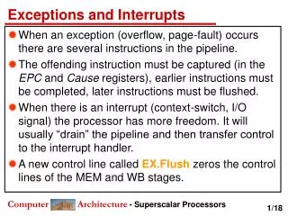
Cortex-M3 Exceptions and Interrupts. Chapter 7, 8, 9 in the reference book. 9.1 Exceptions 9.1.1 Exception Types Exceptions are numbered 1 to 15 for system exceptions and the rest 240 for external interrupt inputs.(Total 256 entries in vector table.)

E N D
9.1 Exceptions 9.1.1 Exception Types Exceptions are numbered 1 to 15 for system exceptions and the rest 240 for external interrupt inputs.(Total 256 entries in vector table.) Most of the exceptions have programmable priority, and a few have fixed priority. The value of the current running exception is indicated by the special register IPSR or from the NVIC’s Interrupt Control State Register.
9.1.2 Definitions of Priority Priority of the exception: A higher-priority exception can preempt (抢占) a lower-priority exception. Reset, NMI, and hard fault have fixed priority levels The Cortex-M3 supports 256 levels of programmable priority. The reduction of priority levels can be implemented by cutting out several lowest bits of the priority configuration register.
3 bits of priority level 4 bits of priority level The minimum number of implemented priority register widths is 3 bits.
Available Priority Levels with 3-Bit or 4-Bit Priority Width
Examples of available exception priority levels for devices with 3-bit, 5-bit, and 8-bit priority registers: Available Priority Levels for Devices with 3-bit, 5-bit, and 8-bit Priority Level Registers
This register is further divided into two parts: preempt priorityand subpriority. Using a Priority Group register, the priority-level configuration register can be divided into two halves, i.e., the upper half (preempt priority) and the lower half (subpriority). • Preempt priority: an interrupt or exception with a higher preempt priority can preempt one with a lower preempt priority • Subpriority: the order when multiple interrupts or exceptions with the same preempt priority occur at the same time
Deciding the Effective Preempt priority and Subpriority Levels
9.1.3 Vector Table The processor will need to locate the starting address of the exception handler when an exception is being handled. This information is stored in the vector table. Exception Vector Table After Power Up
The vector table can be relocated to other locations in the Code or RAM region, done by setting the vector table offset registerin the NVIC. The address offset should be aligned to the vector table size which is rounded to the power of 2. Example: Total IRQ inputs: 32 The total number of exceptions: 32 + 16 (system exceptions) = 48 Extending it to the power of 2: 64. Multiplying it by 4: 256. The vector table offset can be programmed as 0x0, 0x100, 0x200, and so on.
9.1.4 Interrupt Inputs and Pending Behavior When an interrupt input is asserted, it can be pended (pending status is hold by a register) Even if the interrupt source de-asserts the interrupt, the pended interrupt status will still cause the interrupt handler to be executed. Interrupt Pending
If the pending status is cleared (the pending status of the interrupt can be accessed in the NVIC and is writable) before the processor starts responding to the pended interrupt, the interrupt can be canceled. • you can clear a pending interrupt or use software to pend a new interrupt by setting the pending register Interrupt Pending Cleared Before Processor Takes Action
When the processor starts to execute an interrupt, the interrupt becomes active and the pending bit will be cleared automatically. Interrupt Active Status Set as Processor Enters Handler
If an interrupt source continues to hold the interrupt request signal active, the interrupt will be pended again at the end of the interrupt service routine. Continuous Interrupt Request Pends Again After Interrupt Exit
If an interrupt is pulsed several times before the processor starts processing it, it will be treated as one single interrupt request. Interrupt Pending Only Once, Even with Multiple Pulses Before the Handler
If an interrupt is de-asserted and then pulsed again during the interrupt service routine, it will be pended again. Interrupt Pending Occurs Again During the Handler
9.1.5 Fault Exceptions 9.1.5.1 Bus faults Bus faults are produced when an error response is received during a transfer on the AHB interfaces. Bus fault due to:(BFSR Register records the status) 1. Prefetch abort (Instruction prefetch) 2. Data abort (data read/write) 3. Stacking error (stack PUSH in the beginning of interrupt processing) 4. Unstacking error (stack POP at the end of interrupt processing) 5. Reading of an interrupt vector address error (when the processor starts the interrupt-handling sequence)
When these types of bus faults take place If 1. The bus fault handler is enabled (BUSFAULTENA bit in the System Handler Control and State register in the NVIC). 2. No other exceptions with the same or higher priority are running. Then The bus fault handler will be executed. Else if At the same time the core receives another exception handler with higher priority. Then The bus fault exception will be pending. Note: if the bus fault handler is not enabled or when the bus fault happens in an exception handler that has the same or higher priority than the bus fault handler, the hard fault handler will be executed instead
The NVIC has a number of fault status registers. One of them is the Bus Fault Status Register (BFSR). Bus Fault Status Register (0xE000ED29)
9.1.5.2 Memory Management Faults Common memory manage faults include: 1. Access to memory regions not defined in MPU setup. 2. Execute code from nonexecutable memory regions. 3. Writing to read-only regions. 4. An access in the user state to a region defined as privileged access only.
When a memory manage faults occurs if 1. The memory manage fault handler is enabled (set the MEMFAULTENA bit in the System Handler Control and State register in the NVIC). 2. No other exceptions with the same or higher priority are running. Then The memory manage fault handler will be executed. Else if At the same time the core receives another exception handler with higher priority. Then The memory manage fault exception will be pending. Note: If the processor is already running an exception handler with same or higher priority or if the memory management fault handler is not enabled, the hard fault handler will be executed instead.
The NVIC contains a Memory Management Fault Status Register (MFSR) to indicate the cause of the memory management fault. Memory Management Fault Status Register (0xE000ED28)
9.1.5.3 Usage Faults Usage faults can be caused by: 1. Undefined instructions 2. Coprocessor instructions (the Cortex-M3 processor does not support a coprocessor) 3. Trying to switch to the ARM state (This can happen if you load a new value to PC with the LSB equal to 0) 4. Invalid interrupt return (Link Register contains invalid/incorrect values) 5. Unaligned memory accesses using multiple load or store instructions It is possible, by setting up certain control bits in the NVIC, to generate usage faults for: 1. Divide by zero 2. Any unaligned memory accesses
When a usage fault occurs if 1. The usage fault handler is enabled (set the USGFAULTENA bit in the System Handler Control and State register in the NVIC). 2. No other exceptions with the same or higher priority are running. Then The usage fault handler will be executed. Else if At the same time the core receives another exception handler with higher priority. Then The usage fault exception will be pending. Note: If the processor is already running an exception handler with same or higher priority or if the usage fault handler is not enabled, the hard fault handler will be executed instead.
The NVIC provides a Usage Fault Status Register (UFSR) for the usage fault handler to determine the cause of the fault. Usage Fault Status Register (0xE000ED2A)
9.1.5.4 Hard Faults The hard fault handler can be caused by: 1. Usage faults, bus faults, and memory management faults if their handler cannot be executed 2. A bus fault during vector fetch Hard Fault Status Register (0xE000ED2C)
9.1.5.5 Dealing with Faults In a real system, after the cause of a fault is determined (use the Fault Status Registers [FSRs]), the software will have to decide what to do next. If OS exists, the OS could terminates the offending tasks; otherwise, 1. Reset: Using the VECTRESET control bit in the Application Interrupt and Reset Control register in the NVIC (reset the processor core but not the whole chip [using the SYSRESETREQ instead]). 2. Recover: It is possible to resolve the problem that caused the fault exception. Note: The FSRs retain their status until they are cleared manually by using a write-to-clear mechanism (clear by writing 1 to the bits that need to be cleared) in fault handlers
9.1.6 SVC and PendSV SVC (System Service Call) and PendSV (Pended System Call) are two exceptions targeted at software and operating systems. 9.1.6.1 SVC SVC is for generating system function calls. Example: • Instead of allowing user programs to directly access hardware, operating system may provide access to hardware via an SVC. • SVC can make software more portable because the user application does not need to know the programming details of the hardware.
SVC is generated using the SVC instruction. Example: SVC 0x3 ; Call SVC function 3 With the Cortex-M3 interrupt priority model, a SVC cannot be used in a SVC (or other exceptions with higher priority, such as NMI and hard fault) SVC as a Gateway for OS Functions
9.1.6.2 PendSV PendSV (Pended System Call) works with SVC in the OS. PendSV can be pended and is useful for an OS to pend an exception so that an action can be performed after other important tasks(with higher priority) are completed. A typical use of PendSV is context switching (switching between tasks). Example: A system with only two tasks, and a context switch can be triggered by SYSTICK exceptions.
Problems at Context Switching at the IRQ If an interrupt request takes place before the SYSTICK exception, the SYSTICK exception will preempt the IRQ handler. What’s the problem? One solution: context switching can happen only if the OS detects that none of the IRQ handlers are being executed. When the frequency of the IRQ source is close to the SYSTICK?
Another solution: using PendSV which is programmed at lowest priority level
9.2 The NVIC and Interrupt Control 9.2.1 NVIC Overview • The Nested Vectored Interrupt Controller, or NVIC, is an integrated part of the Cortex-M3 processor. • The NVIC supports 1 to 240 external interrupt inputs and a Nonmaskable Interrupt (NMI) input. • The NVIC can be accessed as memory location 0xE000E000. • Most of the interrupt control/ status registers are accessible only in privileged mode (access via MRS and MSR) • Except the Software Trigger Interrupt register, which can be set up to be accessible in user mode • The interrupt control/status register can be accessed in word, half word, or byte transfers • In addition, a few other interrupt-masking registers are also involved in the interrupts.
9.2.2 The Basic Interrupt Configuration • Each external interrupt has several registers associated with: 1. Enable and clear enable registers 2. Set-pending and clear-pending registers 3. Priority level 4. Active status • A number of other registers can also affect the interrupt processing: 1. Exception-masking registers 2. Vector Table Offset register 3. Software Trigger Interrupt register 4. Priority Group
9.2.3 Interrupt Enable and Clear Enable The Interrupt Enable register is programmed via two addresses. To set the enable bit, write 1 to the SETENA register address; To clear the enable bit, write 1 to the CLRENA register address. External interrupts: Up to 240; So for each interrupt NVIC has a SETENA and a CLRENA register. SETENA: 0xE000E100--0xE000E11C CLRENA: 0xE000E180-0xE000E19C
Interrupt Set Enable Registers and Interrupt Clear Enable Registers
9.2.4 Interrupt Pending and Clear Pending If an interrupt takes place but cannot be executed immediately, it will be pended. The interrupt-pending status can be accessed through the Interrupt Set Pending (SETPEND) and Interrupt Clear Pending (CLRPEND) registers. User can set the certain bit of SETPEND to enter its handler by software. Similarly to the enable registers, for each interrupt NVIC has a SETPEND and a CLRPEND register. SETPEND: 0xE000E200-0xE000E21C CLRPEND: 0xE000E280-0xE000E29C
Interrupt Set Pending Registers and Interrupt Clear Pending Registers
9.2.4.1 Priority Each external interrupt has an associated priority-level register (a width of 3-8 bits). Interrupt Priority-Level Registers (0xE000E400-0xE000E4EF)
9.2.4.2 Active Status Each external interrupt has an active status bit. When the processor starts the interrupt handler, the bit is set to 1 and cleared when the interrupt return is executed. Interrupt Active Status Registers (0xE000E300-0xE000E31C)
9.2.4.3 PRIMASK and FAULTMASK Special Registers • The PRIMASK register disables all exceptions except NMI and hard faultby changing the current priority level to 0 • When PRIMASK is set, if a fault takes place, the hard fault handler will be executed) • The FAULTMASK register changes the effective current priority level to 1 so that even the hard fault handler is blocked • FAULTMASK is cleared automatically upon exiting the exception handler. • They are programmable using MRS and MSR instructions. Example: MOV R0, #1 MSR PRIMASK, R0 ; Write 1 to PRIMASK to disable all interrupts MOV R0, #0 MSR PRIMASK, R0 ; Write 0 to PRIMASK to allow interrupts
9.2.4.4 The BASEPRI Special Register The BASEPRI register disables interrupts with priority lower than a certain level. Example: MOV R0, #0x60 MSR BASEPRI, R0 ; Disable interrupts with priority 0x60-0xFF To turn off the masking: MOV R0, #0x0 MSR BASEPRI, R0 ; Turn off BASEPRI masking The BASEPRI register can also be accessed using the BASEPRI_MAX register name.
Using BASEPRI_MAX as a register, it can only be changed to a higher priority level. Example: MOV R0, #0x60 MSR BASEPRI_MAX, R0 ; Disable interrupts with priority 0x60, 0x61,..., etc MOV R0, #0xF0 MSR BASEPRI_MAX, R0 ; This write will be ignored because ; it is lower level than 0x60 MOV R0, #0x40 MSR BASEPRI_MAX, R0 ; This write is allowed and change the masking ; level to 0x40 • To change to a lower masking level or disable the masking, the BASEPRI register name should be used
9.2.4.5 Configuration Registers for Other Exceptions Usage faults, memory management faults, and bus fault exceptions are enabled by the System Handler Control and State Register. The System Handler Control and State Register (0xE000ED24)