Download
1 / 84
900 likes | 1.25k Views
Week 9 MPLS: Multiprotocol Label Switching. MPLS…What is it?. MPLS – Multi-protocol Label Switching can be applied for any layer 2 network protocol MPLS is a natural evolution of Internet It is based on IP and routing protocols such as BGP-4,OSPF and IS-IS

E N D
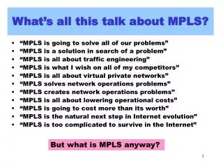
MPLS…What is it? • MPLS – Multi-protocol Label Switching • can be applied for any layer 2 network protocol • MPLS is a natural evolution of Internet • It is based on IP and routing protocols such as BGP-4,OSPF and IS-IS • Typically MPLS resides in service providers networks and not in private networks
MPLS Protocol Stack Application IP or Multi-Service MPLS Layer 2 (PPP, ATM, FR,..) Physical
What is MPLS ? • MPLS provides connection oriented switching based on a label applied at the edge of an MPLS domain. • IP is used to signal MPLS connections. • Major Applications are: • Network Scalability • Traffic Engineering • VPNs
IP MPLS MPLS - Best Of Both Worlds PACKETForwarding PacketSWITCHING HYBRID ATM/FR • Performance • Connection Oriented • Traffic Engineering • Security • QoS • Scalable • Flexible • Easily Deployable • Inexpensive • Dynamic Routing Route at the Edge & Switch at the Core
Why MPLS ? • MPLS converts connectionless IP to a connection- oriented mode • MPLS allows IP to be switched through the Internet instead of routed • With MPLS the first IP packet of a stream establishes a switched path for all subsequent packets to follow • The packets will only be switched at each hop and not routed.
Towards a connection-oriented IP.. • MPLS is the evolution of current IP and connection oriented protocols • Strength and scalability of IP routing • PVC like connectivity • ATM like QoS • Explicit routing Plus • Path protection • Path optimization
MPLS Routers • LER: Label Edge Router • Ingress LER examines inbound packets, classifies packets, adds MPLS header and assigns initial label. • Egress LER removes the MPLS header and routes packets as pure IP • LSR: Label Switch Router • Transit switch that forwards packets based on MPLS labels
IP and MPLS Forwarding • IP packets are classified into FECs (Forwarding Equivalence Class) at each hop based on the destination address in conventional routing • IP packet forwarding works by • assigning a packet to a FEC • determining the next-hop of each FEC • MPLS group Packets by assigning a label in to FECbased on Class of Service (CoS) and forward fast in a defined path with the same forwarding treatment
IP 47.1.1.1 Traditional IP Forwarding 47.1 1 IP 47.1.1.1 2 IP 47.1.1.1 1 3 2 IP 47.1.1.1 1 47.2 3 47.3 2
Label Switch Path (LSP) • LSP: Label Switched Path – Simplex L2 tunnel – Equivalent of Virtual Circuit • 4 Byte Label is inserted in to the IP Packet at egress MPLS node to Switch IP alone the created Label Switch Path (LSP) • Such MPLS nodes are called Label Switch Routers (LSR). • With Labels IP Packet header is analyzed only at ingress and egress LSRs where Labels are inserted and removed. • Labels only have a Local significance and change from hop to hop on the MPLS network. (Like DLCI in FR and VCI/VPI in ATM)
Label Swapping • Label Push: When an IP Packet enters the MPLS network the Label is inserted by ingress LSR • Label Pop: When the IP Packet exits the MPLS network the Label is removed by the egress LSR • The Label is swapped at each intermediate hop based on a Label mapping table • Label mapping table is called the Label Information Base (LIB)
MPLS Header • Label: Label value, 20 bits • Exp: Experimental (CoS), 3 bits • ToS /DSCP to Exp mapping • S: Bottom of stack, 1 bit • TTL: Time to Live, 8 bit – Ingress LER sets MPLS TTL to IP TTL – Egress LER may set IP TTL to MPLS TTL or not
IP Forwarding IP Forwarding LABEL SWITCHING LSR LSR LSR Standard Routing protocols LSR Ingress LSR receives IP packets, performs packet classification (into FECs), assigns a label, & forwards the labeled packet Egress LSR removes label before forwarding IP packets outside MPLS network LSRs forward packets based on the label (no packet classification in the core) Label IP Hdr Payload + MPLS Operation Labels are exchanged . Ingress Egress
MPLS Packet Flow Step 1: Ingress LER classifies IP packet , adds MPLS header and assigns label Step 2: Transit LSR forwards label packet using label swapping Step 3: Egress LER removes MPLS header and performs IP processing
IP 47.1.1.1 IP 47.1.1.1 MPLS IP forwarding via LSP 1 47.1 3 3 2 1 1 2 47.3 3 47.2 2
MPLS Terminology • LDP: Label Distribution Protocol • LSP: Label Switched Path • FEC: Forwarding Equivalence Class • LSR: Label Switching Router • LER: Label Edge Router (Useful term not in standards)
IP1 IP1 IP1 IP2 IP1 IP2 IP1 IP2 #L1 #L1 #L2 #L3 #L3 #L2 IP2 IP2 Forwarding Equivalence Classes LSR LSR LER LER LSP Packets are destined for different address prefixes, but can be mapped to common path • FEC = “A subset of packets that are all treated the same way by a router” • The concept of FECs provides for a great deal of flexibility and scalability • In conventional routing, a packet is assigned to a FEC at each hop (i.e. L3 look-up), in MPLS it is only done once at the network ingress
LABEL SWITCHED PATH (vanilla) #14 #311 #216 #99 #311 #963 #311 #963 #14 #612 #462 #311 #99 #5 - A Vanilla LSP is actually part of a tree from every source to that destination (unidirectional). - Vanilla LDP builds that tree using existing IP forwarding tables to route the control messages.
3 MPLS BUILT ON STANDARD IP 47.1 1 2 1 3 2 1 47.2 3 47.3 2 • Destination based forwarding tables as built by OSPF, IS-IS, RIP, etc.
IP 47.1.1.1 IP FORWARDING USED BY HOP-BY-HOP CONTROL 47.1 1 IP 47.1.1.1 2 IP 47.1.1.1 1 3 2 IP 47.1.1.1 1 47.2 3 47.3 2
Request: 47.1 Request: 47.1 Mapping: 0.40 Mapping: 0.50 MPLS Label Distribution 1 47.1 3 3 2 1 1 2 47.3 3 47.2 2
IP 47.1.1.1 IP 47.1.1.1 Label Switched Path (LSP) 1 47.1 3 3 2 1 1 2 47.3 3 47.2 2
Label Distribution Protocols • The network automatically builds the routing tables by IGP protocols such as OSPF, IS-IS. The label distribution protocol (LDP) uses the established routing topology to route the LSP request path between adjacent LSRs. • A LDP is a set of procedures by which one LSR informs another LSR of the label to FEC bindings it has made. • The LDP also encompasses any negotiations in which two label distribution peers (Ingress LSR and egress LSR) need to engage in order to offer CoS to particular IP stream.
Hop-by-hop routed LSP B A 1 2 1 E 0 0 0 2 2 192.6/16 1 1 2 0 0 D C
EXPLICITLY ROUTED OR ER-LSP Route={A,B,C} #972 #14 #216 #14 #972 #462 B C A - ER-LSP follows route that source chooses. In other words, the control message to establish the LSP (label request) is source routed.
IP 47.1.1.1 IP 47.1.1.1 EXPLICITLY ROUTED LSP ER-LSP 1 47.1 3 3 2 1 1 2 47.3 3 47.2 2
ER LSP - advantages • Operator has routing flexibility (policy-based, QoS-based) • Can use routes other than shortest path • Can compute routes based on constraints in exactly the same manner as ATM based on distributed topology database.(traffic engineering)
Routing Scalability via MPLS Routing Domain C Routing Domain B X W V Z T Y Routing Domain A
Example Contd – Label Stacking Routing Domain C Routing Domain B 6 10 2 12 2 5 X W 17 2 V Z T Y Routing Domain A
R1 R5 R4 R2 R3 Routing Transients • Routing transients happen due to • failure detection (in the order of milliseconds) • LSP dissemination (in the order of propagation delays) • SPF tree calculation (in the order of several hundred milliseconds)
MPLS Example LSR9 LSR8 LSR4 LSR2 Pop 14 LSR1 37 LSR5 LSR7 LSR6 Setup: PATH (ERO = LSR1, LSR2, LSR4, LSR9) Labels established on RESV message
LSR8 LSR9 LSR4 LSR2 Pop LSR1 17 LSR5 LSR7 LSR6 22 Setup: PATH (LSR2, LSR6, LSR7, LSR4) Labels established on RESV message Fast Reroute - Protection Path
LSR8 LSR9 Swap 37 --> 14 Push 17 Pop 14 LSR4 LSR2 Push 37 LSR1 LSR5 LSR7 LSR6 Pop 22 Swap 17 --> 22 Example Label Stack LSR1 LSR2 LSR6 LSR7 LSR4 37 17 22 14 None 14 14
MPLS Protection • May result in suboptimal forwarding but service interruption is negligible • A single protection LSP could be used to fast-route not one but multiple LSPs • Protection on a per-LSP basis (end-to-end) rather than on a per-link basis is also possible • better forwarding properties in case of failures • a single protection may not protect as many LSPs • handles both node and link failures • detection time may be larger • will require the computation of link and node disjoint paths
Label Encapsulation ATM FR Ethernet PPP L2 VPI VCI DLCI “Shim Label” Label “Shim Label” ……. IP | PAYLOAD MPLS Encapsulation is specified over various media types. Top labels may use existing format, lower label(s) use a new “shim” label format.
Traffic Engineering - Objectives • Performance optimization of operational networks. • Reduce congestion hot spots. • Improve resource utilization. • Why current IP routing is not sufficient from TEperspective? Fish problem. • Destination-based • Local optimization
IP Routing & “the Fish” R8 R3 R4 R5 R2 R1 R6 R7 IP (Mostly) Uses Destination-Based Least-Cost Routing Flows from R8 and R1 Merge at R2 and Become Indistinguishable From R2, Traffic to R3, R4, R5 Use Upper Route Alternate Path Under-Utilized 6
Deficiencies in IP Routing • Chronic local congestion • Load balancing • Across long haul links • Size of links • Difficult to get IP to make good use unequal size links without overloading the lower speed link
Peer Model • Peer model • OSPF routing + link weights. • Key technique: weight setting. • Networks operate as it does today. • Much more scalable than overlay model.
Load Balancing Making good use of expensive links simply by adjusting IGP metrics can be a frustrating exercise!
Overlay Motivation “The use of the explicit Layer 2 transit layer gives us very exacting control of how traffic uses the available bandwidth in ways not currently possible by tinkering with Layer 3-only metrics.” Separate Layer 2 Network (Frame Relay or ATM)
The Overlay Solution L3 • Layer 2 (for example ATM) network used to manage the bandwidth • Layer 3 sees a complete mesh L3 L3 L3 L2 L2 L3 L2 L3 L3 L3 L2 L2 L2 L3 L3 L3 L3 Physical Logical
Overlay Drawbacks • Extra network devices (cost) • More complex network management • Two-level network without integrated NM • Additional training, technical support, field engineering • IGP routing doesn’t scale for meshes • Number of LSPs generated for a failed router is O(n3); n = number of routers
Overlay Drawbacks • Every router is permanently connected to every other router (fullmesh) • PVCs are provisioned with given bandwidths • Delays are short • Problem: scalability • For N routers, N x (N-1)/2 ATM VCs • Also: • The IP link-state routing protocol (e.g. OSPF) has to handle ahuge number of links, and link State Advertisements packets are flooded on every link • Worse: when an ATM link fails, all VCs using that link fail, andmany IP routers have to update their routing tables at the sametime • Amount of routing information can be as much as N^4 • In practice, this solution does not scale beyond 100 routers (± 5000PVCs)
or + = MPLS Router Router ATM Switch Traffic Engineering & MPLS • MPLS fuses Layer 2 and Layer 3 • Layer 2 capabilities of MPLS canbe exploited for IP traffic engineering • Single box / network solution ATM MPLS Router
Labels, like VCIs can be used to establish virtual circuits Normal Route R1->R2->R3->R4->R5 Tunnel: R1->R2->R6->R7->R4 An LSP Tunnel R8 R3 R4 R5 R2 R1 R6 R7
Comprehensive Traffic Engineering • Network design • Engineer the topology to fit the traffic • Traffic engineering • Engineer the traffic to fit the topology • Given a fixed topology and atraffic matrix, what set of explicit routes offers the best overall network performance?