Download
1 / 81
940 likes | 1.4k Views
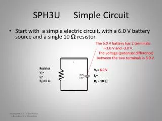
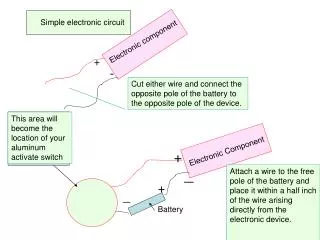
+. Simple Electrical Circuit pictorial . Simple Electrical Circuit schematic. A voltage divider used for volume control. Block Diagram Drawing. Standard symbol for a dc voltage source . electrical schematic of flashlight. Resistance symbol and notation. Film resistors:.

E N D
A voltage divider used for volume control. Block Diagram Drawing
Color-code bands on a resistor • 1st band is the first digit of the resistance value • 2nd band is the second digit of the resistance value • 3rd band is the multiplier (number of zeros) • 4th band indicates the tolerance
Potentiometer and rheostat symbols and basic construction of one type of potentiometer.
Circuit Ground • Voltage is relative • The voltage at one point in a circuit is always measured relative to another point • This reference point in a circuit is usually the ground point
Notation Voltage sources and grounds Ground symbol Voltage source symbol
Using an ohmmeter to measure the total resistance of a series circuit.
The voltage divider as a bias circuit for a transistor amplifier.
Relative sizes of different types of inductors: (a) toroid, high-current; (b) phenolic (resin or plastic core); (c) ferrite core.
(a) Film/foil polyester radial lead; (b) metalized polyester-film axial lead; (c) surface-mount polyester-film; (d) polypropylene-film, radial lead.
Capacitors Variable Capacitors • Most common are shown in the figure below. The dielectric for each is air. The capacitance is changed by turning the shaft at one end to vary the common area of the movable and fixed plates. The greater the common area the larger the capacitance.
Symbol for a sinusoidal voltage source. Volts A.C.
Some common types of transformers(step AC voltage up or down)
Utility-pole transformer in a typical power distribution system.
Connections Wire To pass current very easily from one part of a circuit to another A ‘DOT' should be drawn where wires are connected (joined), but it is sometimes omitted.
Connections • In complex diagrams it is often necessary to draw wires crossing even though they are not connected, the 'bridge' symbol shown on the right is preferred because the simple crossing on the left may be misread as a join where you have forgotten to add a ‘DOT'!