Download
1 / 44
450 likes | 551 Views
Network+ Guide to Networks 5 th Edition. Chapter 8 Wireless Networking. Objectives. Explain how nodes exchange wireless signals Identify potential obstacles Understand WLAN (wireless LAN) architecture

E N D
Network+ Guide to Networks5th Edition Chapter 8 Wireless Networking
Objectives • Explain how nodes exchange wireless signals • Identify potential obstacles • Understand WLAN (wireless LAN) architecture • Specify characteristics of popular WLAN transmission methods, including 802.11 a/b/g/n • Install/configure wireless access points and their clients • Describe wireless MAN and WAN technologies, including 802.16 and satellite communications
Wireless Spectrum • Continuum of electromagnetic waves • Data, voice communication; Arranged by frequencies-Lowest to highest • Spans 9 KHz and 300 GHz • Wireless services associated with one area • Ex. AM broadcasting 535-1605 KHz; most cordless phones 2.4 GHz • FCC oversees United States frequencies • ITU oversees international frequencies • Air signals propagate across borders
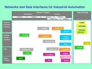
Figure 8-2 Wireless transmission and reception Characteristics of Wireless Transmission • Similarities with wired • Layer 3 and higher protocols • Signal origination • From electrical current, travel along conductor • Differences from wired • Signal transmission • No fixed path, guidance • Antenna • Signal transmission and reception • Same frequency required on each antenna • Share same channel
Antennas • Radiation pattern • Relative strength over three-dimensional area • All electromagnetic energy antenna sends, receives • Directional antenna • Issues wireless signals along single direction • Omnidirectional antenna • Issues and receives wireless signals • Equal strength and clarity in all directions • Range • Reachable geographical area
Figure 8-3 Multipath signal propagation Signal Propagation • LOS (line-of-sight) • Signal travels • In straight line, directly from transmitter to receiver • Uses least amount of energy; results in reception of the clearest possible signal • Obstacles affect signal travel • Pass through them or absorb into them • Subject signal to 3 phenomena • Reflection: bounce back to source • Diffraction: splits into secondary waves; caused by objects with sharp edges • Scattering: diffusion in multiple different directions (rough surfaces, outdoors) • Multipath signals • Wireless signals follow different paths to destination • Caused by reflection, diffraction, scattering • Advantage-Better chance of reaching destination • Disadvantage-Signal delay
Signal Degradation • Fading • Change in signal strength • Electromagnetic energy scattered, reflected, diffracted • Attenuation • Signal weakens • Moving away from transmission antenna • Correcting signal attenuation • Amplify (analog), repeat (digital) • Noise • Significant problem • No wireless conduit, shielding (EMI)
Frequency Ranges • 2.4-GHz band (older) • Frequency range: 2.4–2.4835 GHz • 11 unlicensed communications channels • Susceptible to interference • Unlicensed • No FCC registration required • 5-GHz band (newer) • Frequency bands • 5.1 GHz, 5.3 GHz, 5.4 GHz, 5.8 GHz • 24 unlicensed bands, each 20 MHz wide • Used by weather, military radar communications
Narrowband, Broadband, and Spread Spectrum Signals • Defines wireless spectrum use: • Narrowband • Transmitter concentrates signal energy at single frequency, very small frequency range • Broadband • Relatively wide wireless spectrum band • Higher throughputs than narrowband • Spread-spectrum • Multiple frequencies used to transmit signal • Offers security • FHSS (frequency hopping spread spectrum) • Signal jumps between several different frequencies within band • Synchronization pattern known only to channel’s receiver, transmitter • DSSS (direct-sequence spread spectrum) • Signal’s bits distributed over entire frequency band at once • Each bit coded • Receiver reassembles original signal upon receiving bits
Fixed versus Mobile • Fixed communications wireless systems • Transmitter, receiver locations do not move • Transmitting antenna focuses energy directly toward receiving antenna • Point-to-point link results • Advantage • No wasted energy issuing signals; predictable • More energy used for signal itself • Mobile communications wireless systems • Receiver located anywhere within transmitter’s range • Receiver can roam
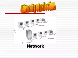
Figure 8-4 Ad hoc WLAN WLAN (Wireless LAN) Architecture • Ad hoc WLAN • Wireless nodes transmit directly to each other • Use wireless NICs • No intervening connectivity device • Poor performance • Many spread out users, obstacles block signals • Access point (AP) • Accepts wireless signals from multiple nodes • Retransmits signals to network • Base stations, wireless routers, wireless gateways
Figure 8-5 An infrastructure WLAN WLAN Architecture (cont’d.) • Infrastructure WLAN • Stations communicate with access point • Not directly with each other • Access point requires sufficient power, strategic placement • WLAN may include several access points • Dependent upon number of stations • Maximum number varies: 10-100
Figure 8-6 Wireless LAN interconnection WLAN Architecture (cont’d.) • Mobile networking allows roaming wireless nodes • Range dependent upon wireless access method, equipment manufacturer, office environment • Access point range: 300 feet maximum • Can connect 2 separate LANs • Fixed link, directional antennas between two access points • Allows access points 1000 feet apart • Support for same protocols, operating systems as wired LANs • Ensures compatibility
802.11 WLANs • Wireless technology standard • Describes unique functions • Physical and Data Link layers • Differences • Specified signaling methods, geographic ranges, frequency usages • Developed by IEEE’s 802.11 committee • Wi-Fi (wireless fidelity) standards • 802.11b, 802.11a, 802.11g, 802.11n • Share characteristics • Half-duplexing, access method, frame format
Access Method • 802.11 MAC services • Append 48-bit (6-byte) physical addresses to frame • Identifies source, destination • Same physical addressing scheme as 802.3 • Allows easy combination • Wireless devices • Not designed for simultaneous transmit, receive • Cannot quickly detect collisions • Use different access method • CSMA/CA (Carrier Sense Multiple Access with Collision Avoidance) • Minimizes collision potential • Uses ACK packets to verify every transmission • Requires more overhead than 802.3 • Real throughput less than theoretical maximum • RTS/CTS (Request to Send/Clear to Send) protocol • Optional • Ensure packets not inhibited by other transmissions • Efficient for large transmission packets • Further decreases overall 802.11 efficiency
Figure 8-7 A network with a single BSS Association • Packet exchanged between computer, access point • Gain Internet access • Scanning • Surveying surroundings for access point • Active scanning transmits special frame • Probe • Passive scanning listens for special signal • Beacon fame • SSID (service set identifier) • Unique character string identifying access point • In beacon fame information • Configured in access point • Better security, easier network management • BSS (basic service set) • Station groups sharing access point • BSSID (basic service set identifier) • Station group identifier
Figure 8-8 A network with multiple BSSs forming an ESS Association (cont’d.) • ESS (extended service set) • Access point group connecting same LAN • Share ESSID (extended service set identifier) • Allows roaming • Station moving from one BSS to another without losing connectivity • Several access points detected • Select strongest signal, lowest error rate • Poses security risk • Powerful, rogue access point • ESS with several authorized access points • Must allow station association with any access point • While maintaining network connectivity • Reassociation • Mobile user moves from one access point’s range into another’s range • Occurs by simply moving, high error rate • Stations’ scanning feature • Used to automatically balance transmission loads • Between access points
Frames Figure 8-9 Basic 802.11 data frame • 802.11 networks overhead • ACKs, probes, beacons • 802.11 specifies MAC sublayer frame type • Multiple frame type groups • Control: association and reassociation • Probe, beacon frames • Management: medium access, data delivery • ACK and RTS/CTS frames • Data: carry data sent between stations • 802.11 data frame overhead • Four address fields • Source address, transmitter address, receiver address, destination address • Sequence Control field • How large packet fragmented • Frame Control field • Wi-Fi share MAC sublayer characteristics • Wi-Fi differ in modulation methods, frequency, usage, ranges
802.11b • DSSS (direct-sequence spread spectrum) signaling • 2.4-GHz band • Separated into 22-MHz channels • Throughput • 11-Mbps theoretical • 5-Mbps actual • 100 meters node limit • Oldest, least expensive • Being replaced by 802.11g
802.11a • Released after 802.11b • 5-GHz band • Not congested like 2.4-GHz band • Lower interference, requires more transmit power • Throughput • 54 Mbps theoretical • 11 and 18 Mbps effective • Attributable to higher frequencies, unique modulating data method, more available bandwidth • 20 meter node limit • More expensive, least popular
802.11g • Affordable as 802.11b • Throughput • 54 Mbps theoretical • 20 to 25 Mbps effective • 100 meter node range • 2.4-GHz frequency band • Compatible with 802.11b networks
802.11n • Manufacturers • Selling 802.11n-compatible transceivers • Primary goal • Wireless standard providing much higher effective throughput • Maximum throughput: 600 Mbps • Threat to Fast Ethernet • Backward compatible with 802.11a, b, g standards • 2.4-GHz or 5-GHz frequency range • Compared with 802.11a, 802.11g • Same data modulation techniques • Compared with three 802.11 standards • Manages frames, channels, encoding differently • Allows high throughput
Figure 8-10 802.11n access point with three antennas 802.11n (cont’d.) • MIMO (multiple input-multiple output) • Multiple access point antennas may issue signal to one or more receivers • Increases network’s throughput, access point’s range • Channel bonding • Two adjacent 20-MHz channels bonded to make 40-MHz channel • Doubles bandwidth available in single 20-MHz channel • Bandwidth reserved as buffers assigned to carry data • Higher modulation rates • Single channel subdivided into multiple, smaller channels • More efficient use of smaller channels • Different encoding methods
Figure 8-11 Aggregated 802.11n frame 802.11n (cont’d.) • Frame aggregation • Combine multiple frames into one larger frame • Advantage: reduces overhead • Maximum throughput dependencies • Number, type of strategies used • 2.4-GHz or 5-GHz band • Actual throughput: 65 to 600 Mbps • Backward compatible • Not all 802.11n features work • Recommendation • Use 802.11n-compatible devices
Bluetooth Networks • Ericson’s original goals • Wireless technology compatible with multiple devices • Require little power • Cover short ranges • Aim of Bluetooth Special Interest Group (SIG) • Refine and standardize technology • Result: Bluetooth • Mobile wireless networking standard using FHSS (frequency hopping spread spectrum) RF signaling in 2.4-GHz band • Version 1.1 • Maximum theoretical throughput: 1 Mbps • Effective throughput: 723 Kbps • 10 meter node difference • Designed for PANs (personal area networks) • Version 2.0 (2004) • Different encoding schemes • 2.1-Mbps throughput • 30 meters node difference • Usage: cellular telephones, phone headsets, computer peripherals, PDAs
Table 8-1 Wireless standards Summary of WLAN Standards
Implementing a WLAN • Designing a small WLAN • Home, small office • Formation of larger, enterprise-wide WANs • Installing and configuring access points and clients • Implementation pitfalls • Avoidance • Material applies to 802.11b and 802.11g • Most popular
Figure 8-12 Home or small office WLAN arrangement Determining the Design • One access point • Combine with switching, routing functions • Connects wireless clients to LAN • Acts as Internet gateway • Access point WLAN placement considerations • Typical distances between access point and client • Obstacles • Type, number between access point and clients
Figure 8-13 Enterprise-wide WLAN Determining the Design (cont’d.) • Larger WLANs • Systematic approach to access point placement • Site survey • Assesses client requirements, facility characteristics, coverage areas • Determines access point arrangement ensuring reliable wireless connectivity • Within given area • Proposes access point testing • Testing wireless access from farthest corners • Install access points • Must belong to same ESS, share ESSID • Enterprise-wide WLAN design considerations • How wireless LAN portions will integrate with wired portions
Figure 8-14 The Netgear router Basic Settings page Configuring Wireless Connectivity Devices • Netgear WGR614 (v7) • Popular, low-cost access point • Four switch ports, routing capabilities • Supports 802.11b, 802.11g transmission • Configuration steps on other small wireless connectivity devices • Differ somewhat • Follow similar process, modify same variables
Figure 8-15 Netgear router Wireless Settings page Figure 8-16 The Netgear router Advanced Wireless Settings page
Figure 8-17 Netgearrouter LAN IP Setup page Figure 8-18 Netgearrouter Router Status page
Configuring Wireless Clients • Configuration varies from one client type to another • Windows XP client WLAN configuration • Use graphical interface • Linux and UNIX clients wireless interface configuration • Use graphical interface • iwconfig command-line function • View, set wireless interface parameters
Configuring Wireless Clients (cont’d.) Figure 8-21 Output from iwconfig command
Avoiding Pitfalls • Access point versus client configurations • SSID mismatch • Incorrect encryption • Incorrect channel, frequency • Standard mismatch (802.11 a/b/g/n) • Incorrect antenna placement • Verify client within 330 feet • Interference • Check for EMI sources
Wireless WANs and Internet Access • Wireless broadband • Latest wireless WAN technologies • Specifically designed for: • High-throughput, long-distance digital data exchange
802.11 Internet Access • Access points: 802.11b or 802.11g access methods • Hot spots • Places with publicly available wireless Internet access • Free or subscription • Hot spot subscription Internet access • Log on via Web page • Client software managing client’s connection • Network log on, secure data exchange • Added security: accept connection based on MAC address • Accept user’s connection based on MAC address
802.16 (WiMAX) Internet Access • WiMAX (Worldwide Interoperability for Microwave Access) • Current version: 802.16e (2005) • Improved mobility, QoS characteristics • Digital voice signals, mobile phone users • Functions in 2 and 66 GHz range • Licensed, nonlicensed frequencies • line-of-sight paths between antennas • Throughput potential maximized • Non-line-of-sight paths • Exchange signals with multiple stations at once
802.16 (WiMAX) Internet Access (cont’d.) • Two distinct advantages over Wi-Fi • Much greater throughput (70 Mbps) • Much farther range (30 miles) • Appropriate for MANs and WANs • Highest throughput achieved over shortest distances between transceivers • Possible uses • Alternative to DSL, broadband cable • Well suited to rural users • Internet access to mobile computerized devices • Residential homes
Figure 8-24 WiMAX service provider’s antenna Figure 8-23 WiMAX residential antenna 802.16 (WiMAX) Internet Access (cont’d.) • Metropolitan area installation • Home antenna, connectivity device eliminated • WiMAX MANs • Extensive connectivity • Download data rates faster than home broadband connection • Shared service • Apportioned bandwidth • Drawback • Expensive Figure 8-22 WiMAX residential service installation
Satellite Internet Access • Used to deliver: • Digital television and radio signals • Voice and video signals • Cellular and paging signals • Provides homes and businesses with Internet access
Satellite Orbits • Geosynchronous orbit • Satellites orbit the Earth at the same rate as the Earth turns • Downlink • Satellite transponder transmits signal to Earth-based receiver • Typical satellite • 24 to 32 transponders • Unique downlink frequencies • LEO (low Earth orbiting) satellites • Orbit Earth with altitude 100 miles to 1240 miles • Not positioned over equator • MEO (medium Earth orbiting) satellites • Orbit Earth 6000 to 12,000 miles above surface • Not positioned over equator • Latitude between equator and poles • Advantage • Cover larger Earth surface area than LEO satellites • Less power, less signal delay than GEO satellites • Geosynchronous orbiting satellites most popular for satellite Internet access Figure 8-25 Satellite communication
Satellite Frequencies • Five frequency bands • L-band—1.5–2.7 GHz • S-band—2.7–3.5 GHz • C-band—3.4–6.7 GHz • Ku-band—12–18 GHz • Ka-band—18–40 GHz • Within bands • Uplink, downlink transmissions differ • Satellite Internet access providers • Use C- or Ku-bands and Ka-band (future)
Figure 8-26 Dial return satellite Internet service Satellite Internet Services • Subscriber • Small satellite dish antenna, receiver • Exchanges signals with provider’s satellite network • Satellite Internet access service • Dial return arrangement (asymmetrical) • Receives Internet data via downlink transmission • Sends data to satellite via analog modem connection • Satellite return arrangement (symmetrical) • Send, receive data to and from Internet using satellite uplink and downlink