Download
1 / 51
780 likes | 1.43k Views
Chapter 02 Logic Design with MOSFETs. Introduction to VLSI Circuits and Systems 積體電路概論. 賴秉樑 Dept. of Electronic Engineering National Chin-Yi University of Technology Fall 2007. Outline. The Fundamental MOSFETs Ideal Switches and Boolean Operations MOSFETs as Switches

E N D
Chapter 02Logic Design with MOSFETs Introduction to VLSI Circuits and Systems積體電路概論 賴秉樑 Dept. of Electronic Engineering National Chin-Yi University of Technology Fall 2007
Outline • The Fundamental MOSFETs • Ideal Switches and Boolean Operations • MOSFETs as Switches • Basic Logic Gates in CMOS • Complex Logic Gates in CMOS • Transmission Gate Circuits • Clocking and Dataflow Control
p-n Junction • A junction between p-type and n-type semiconductor forms a diode • Current flows only in one direction cathode anode P N
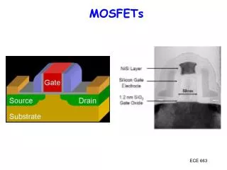
nMOS Transistor • Four terminals: gate (G), source (S), drain (D), body (B) • Gate–oxide–body stack looks like a capacitor • Gate and body are conductors • SiO2 (oxide) is a very good insulator • Called metal – oxide – semiconductor (MOS) capacitor • Even though gate is no longer made of metal
nMOS Operation (1/2) • Body is usually tied to ground (0 V) • When the gate is at a low voltage • P-type body is at low voltage • Source-body and drain-body diodes are OFF • No current flows, transistor is OFF
nMOS Operation (2/2) • When the gate is at a high voltage • Positive charge on gate of MOS capacitor • Negative charge attracted to body • Inverts a channel under gate to n-type • Now current can flow through n-type silicon from source through channel to drain, transistor is ON
pMOS Transistor • Similar, but doping and voltages reversed • Body tied to high voltage (VDD) • Gate “low”: transistor ON • Gate “high”: transistor OFF • Bubble indicates inverted behavior
Outline • The Fundamental MOSFETs • Ideal Switches and Boolean Operations • MOSFETs as Switches • Basic Logic Gates in CMOS • Complex Logic Gates in CMOS • Transmission Gate Circuits • Clocking and Dataflow Control
Ideal Switches (1/3) • CMOS integrated circuits use bi-directional devices called MOSFETs as logic switches • Controlled switches, e.g, assert-high and assert-low switches • An assert-high switch is showing in Figure 2.1 (a) Open (b) Closed Figure 2.1 Behavior of an assert-high switch
Ideal Switches (2/3) g = (a.1) .b = (a.1) .b Figure 2.2 Series-connected switches g = (a.1) + (b.1) = a + b Figure 2.4 Parallel-connected switches
Ideal Switches (3/3) Figure 2.6 Series-connected complementary switches (a) Closed (b) Open Figure 2.8 A MUX-based NOT gate Figure 2.5 An assert-low switch Figure 2.7 An assert-low switch
Outline • The Fundamental MOSFETs • Ideal Switches and Boolean Operations • MOSFETs as Switches • Basic Logic Gates in CMOS • Complex Logic Gates in CMOS • Transmission Gate Circuits • Clocking and Dataflow Control
MOSFET as Switches • MOSFET: Metal-Oxide-Semiconductor Field-Effect Transistor • nFET: an n-channel MOSFET that uses negatively charged electrons for electrical current flow • pFET: a p-channel MOSFET that uses positive charges for current flow • In many ways, MOSFETs behave like the idealized switches introduced in the previous section • The voltage applied to the gate determines the current flow between the source and drain terminals (a) nFET symbol (b) pFET symbol Figure 2.9 Symbols used for nFETs and pFETs
MOSFET as Switches • Early generations of silicon MOS logic circuits used both positive and negative supply voltages as Figure 2.10 showing • In modern designs require only a single positive voltage VDD and the ground connection, e.g. VDD= 5 V and 3.3 V or lower • The relationship between logic variables x and it’s voltages Vx Figure 2.10 Dual power supply voltages (2.14) (2.15) (a) Power supply connection (b) Logic definitions Figure 2.11 Single voltage power supply
Switching Characteristics of MOSFET • In general, • The transition region between the highest logic 0 voltage and the lowest logic 1 voltage is undefined • nFET • pFET • Low voltages correspond to logic 0 values • High voltages correspond to logic 1 values (a) Open (b) Closed Figure 2.12 nFET switching characteristics (2.16) (b) Closed (a) Open (2.17) Figure 2.13 pFET switching characteristics
nMOS FET Threshold Voltages • An nFET is characterized by a threshold voltage VTn that is positive, typical is around VTn= 0.5 V to 0.7 V • If , then the transistor acts like an open (off) circuit and there is no current flow between the drain and source • If , then the nFET drain and source are connected and the equivalent switch is closed (on) • Thus, to define the voltage VA that is associated with the binary variable A (a) Gate-source voltage (2.20) (b) Logic translation Figure 2.14 Threshold voltage of an nFET
pMOS FET Threshold Voltages • An pFET is characterized by a threshold voltage VTp that is negative, typical is around VTp = –0.5 V to –0.8 V • If , then the transistor acts like an open (off) switch and there is no current flow between the drain and source • If , then the pFET drain and source are connected and the equivalent switch is closed (on) • Thus, to the applied voltage VA we first sum voltage to write (a) Source-gate voltage (2.23) (2.26) (2.24) (b) Logic translation (2.25) Figure 2.15 pFET threshold voltage Note that the transition between a logic 0 and a logic 1 is at (2.25) !
nFET Pass Characteristics • An ideal electrical switch can pass any voltage applied to it • As Figure 2.16(b), the output voltage Vy is reduced to a value • Which is less than the input voltage VDD, called threshold voltage loss • Thus, we say that the nFET can only pass a weaklogic 1; in other word, the nFET is said to pass a stronglogic 0 can pass a voltage in the range [0, V1] since (2.27) (a) Logic 0 transfer (b) Logic 1 transfer Figure 2.16 nFET pass characteristics
pFET Pass Characteristics • Figure 2.17(a) portrays the case where Vx = VDD corresponding to a logic 1 input. The output voltage is • Figure 2.17(b), the transmitted voltage can only drop to a minimum value of • The results of the above discussion • nFETs pass strong logic 0 voltages, but weak logic 1 values • pFETs pass strong logic 1 voltages, but weak logic 0 levels • Use pFETs to pass logic 1 voltages of VDD • Use nFETs to pass logic 0 voltages of VSS = 0 V ,which is an ideal logic 1 level (2.29) (a) Logic 0 transfer since (2.30) (b) Logic 1 transfer Figure 2.17 pFET pass characteristics
Outline • The Fundamental MOSFETs • Ideal Switches and Boolean Operations • MOSFETs as Switches • Basic Logic Gates in CMOS • Complex Logic Gates in CMOS • Transmission Gate Circuits • Clocking and Dataflow Control
Basic Logic Gates in CMOS • Digital logic circuits are nonlinear networks that use transistors as electronic switches to divert one of the supply voltages VDD or 0 V to the output • The general switching network (a) f = 1 output (b) f = 0 output Figure 2.18 General CMOS logic gate Figure 2.19 Operation of a CMOS logic gate
The NOT Gate (1/2) (a) x = 0 input (a) Logic symbol Figure 2.20 A complementary pair (b) x = 1 input (b) Truth Table Figure 2.21 Operation of the complementary pair Figure 2.22 NOT gate
The NOT Gate (2/2) (a) x = 0 input (b) x = 1 input Figure 2.23 CMOS not gate Figure 2.24 Operation of the CMOS NOT gate
The NOR Gate (1/2) (a) Logic symbol (a) Logic diagram Figure 2.27 NOR2 gate Karnaugh map (b) Voltage network (b) Truth Table Figure 2.26 NOR2 using a 4:1 multiplexor Figure 2.25 NOR logic gate
NOR (2/2) Figure 2.28 NOR2 in CMOS Figure 2.30 NOR3 in CMOS Figure 2.29 Operational summary of the NOR2 gate
NAND (1/2) (a) Logic symbol (a) Logic diagram Figure 2.33 NAND2 K-map (b) Voltage network (b) Truth Table Figure 2.32 NAND2 using 4:1 multiplexor Figure 2.31 NAND2 logic gate
NAND (2/2) Figure 2.34 CMOS NAND2 logic circuit Figure 2.36 NAND3 in CMOS Figure 2.35 Operational summary of the NAND2 gate
Outline • The Fundamental MOSFETs • Ideal Switches and Boolean Operations • MOSFETs as Switches • Basic Logic Gates in CMOS • Complex Logic Gates in CMOS • Transmission Gate Circuits • Clocking and Dataflow Control
Complex Logic Gate (1/3) • Complex or combinational logic gates • Useful in VLSI system-level design • Consider a Boolean expression • Expanding by simply ANDing the result with a logical 1 (2.50) (2.51)
Complex Logic Gate (2/3) nFET array that gives F=0 when necessary Figure 2.37 Logic function example Figure 2.39 nFET circuit for F Figure 2.40 Karnaugh for nFET circuit Figure 2.38 pFET circuit for F function from equation (2.51)
Complex Logic Gate (3/3) • The characteristics of Complementary CMOS • 對於CMOS電路而言,由於完全對稱的結構,若是輸入電壓有 0 ~ VDD的全擺幅(full swing) ,則輸出訊號也ㄧ定擁有VDD ~ 0 (反相) 的全擺幅。同時當輸入電壓是0或是VDD時,電路也沒有直流功率消耗。 • 由於輸入及輸出訊號均有全擺幅,任何閘級均能任意銜接,不需考慮電壓準位問題。 • 也由於輸入及輸出訊號均有全擺幅,製程變動也不會影響此特性。所以縱然製造後製程特性可能與設計時稍有不同,對於ㄧ般的CMOS電路,或許會影響其速度或功率消耗等電性的表現,卻不會影響其應有的功能(function)。此點對於所謂的超大型積體電路而言是一項大利多,因為它為大型電路之量產(mass production)特性提供了一個絕佳的支持–即可靠度(reliability) 。 • 更由於上述特性,一般在設計時均會考慮環境因素的變動範圍(variation corners),讓設計除了滿足功能要求外,也讓電性的表現甚至比規格 (specifications)還嚴一點,亦即留有寬限(margin)。因此製造後,非但功能ㄧ定可以達成,電性也能滿足規格。 Figure 2.41 Finished complex CMOS logic gate circuit
Structured Logic Design (1/4) • CMOS logic gates are intrinsically inverting • Output always produces a NOT operation acting on the input variables Figure 2.42 Origin of the inverting characteristic of CMOS gates
Structured Logic Design (2/4) (a) Series-connected nFETs Figure 2.44 nFET AOI circuit (b) Parallel-connected nFETs Figure 2.45 nFET OAI circuit Figure 2.43 nFET logic formation
Structured Logic Design (3/4) (a) Parallel-connected pFETs (a) pFET AOI circuit (b) pFET OAI circuit (b) Series-connected pFETs Figure 2.47 pFET arrays for AOI and OAI gates Figure 2.46 pFET logic formation
Structured Logic Design (4/4) (a) AOI circuit (b) OAI circuit Figure 2.48 Complete CMOS AOI and OAI circuits
Bubble Pushing (a) NAND - OR (a) Parallel-connected pFETs (b) NOR - AND Figure 2.52 Bubble pushing using DeMorgan rules (b) Series-connected pFETs Figure 2.51 Assert-low models for pFETs
XOR and XNOR Gates • An important example of using an AOI circuit is constructing Exclusive-OR (XOR) and Exclusive-NOR circuits (2.71) (2.72) (2.73) (a) Exclusive-OR (b) Exclusive-NOR (2.74) Figure 2.57 AOI XOR and XNOR gates (a) AOI22 (b) AOI321 (c) AOI221 Figure 2.58 General naming convention Figure 2.56 XOR
Outline • The Fundamental MOSFETs • Ideal Switches and Boolean Operations • MOSFETs as Switches • Basic Logic Gates in CMOS • Complex Logic Gates in CMOS • Transmission Gate Circuits • Clocking and Dataflow Control
Transmission Gate Circuits • A CMOS TG is created by connecting an nFET and pFET in parallel • Bi-directional • Transmit the entire voltage range [0, VDD] (2.78) Figure 2.60 Transmission gate (TG)
Analysis of CMOS TG (1/4) • Four representations of CMOS Transmission Gate (TG)
Region I Region II Region III nMOS: cut-off pMOS: linear reg. nMOS: saturation pMOS: saturation nMOS: saturation pMOS: linear reg. Vout |Vt,p| (VDD-Vt,n) VDD 0V Analysis of CMOS TG (2/4) • Case (A) Vin=Vdd, C=Vdd (Both transistors ON) PMOS is always ON regardless of Vout Value • Total Current from I/P to O/P: ID = IDS,n+ISD,p • Equivalent resistance of NMOS and PMOS • Equivalent R of TG = reg,n // reg,p Summary of operating regions of MOS
Region 1 Region 2 Region 3 nMOS: cut-off pMOS: linear reg. nMOS: saturation pMOS: saturation nMOS: saturation pMOS: linear reg. Vout |Vt,p| (VDD-Vt,n) VDD 0V Analysis of CMOS TG (3/4) NMOS: saturation PMOS: saturation • Region (I): Vout < |Vt,p| { NMOS: saturation PMOS: linear reg. • Region (II): |Vt,p| < Vout < (VDD-Vt,n) { • Note: • NMOS source-to-substrate voltage = VSB,n = Vout - 0 = Vout (Body Effect) • PMOS source-to-substrate voltage = VSB,p = 0 - 0 = 0 (constant) (Vds)2 (Vgs-Vt) Vds
Region 1 Region 2 Region 3 nMOS: cut-off pMOS: linear reg. nMOS: saturation pMOS: saturation nMOS: saturation pMOS: linear reg. Vout |Vt,p| (VDD-Vt,n) VDD 0V Analysis of CMOS TG (4/4) NMOS: cut-off PMOS: linear reg. • Region (III): Vout > (VDD-|Vt,p|) { • Total resistance of CMOS TG v.s. Vout • Equivalent resistance of TG is relatively constant • Individual reg. of NMOS and PMOS are strongly dependent on Vout!!
Logic Design using TG (1/3) • Multiplexors • TG based 2-to-1 multiplexor • The 2-to-1 extended to a 4:1 network by using the 2-bit selector word (s1, so) (2.79) Figure 2.61 A TG-based 2-to-1 multiplexor (2.80)
Logic Design using TG (2/3) • TG based XOR/XNOR • TG based OR gate (2.81) (2.82) (b) XNOR circuit (a) XOR circuit Figure 2.62 TG-based exclusive-OR and exclusive-NOR circuits (2.83) Figure 2.63 A TG-based OR gate
Logic Design using TG (3/3) • Alternate XOR/XNOR Circuits • Mixing TGs and FETs which are designed for exclusive-OR and equivalence (XNOR) functions • It’s important in adders and error detection/correction algorithms Figure 2.64 An XNOR gate that used both TGs and FETs
Outline • The Fundamental MOSFETs • Ideal Switches and Boolean Operations • MOSFETs as Switches • Basic Logic Gates in CMOS • Complex Logic Gates in CMOS • Transmission Gate Circuits • Clocking and Dataflow Control
Clock and Dataflow Control • Synchronous digital design using a clock signal • Simply, the switching characteristics of TGs • As Figure 2.66(b), when TG is off, the value of y = x for a very short time thold. If we use a high-frequency clock then the periodic open-closed change occurs at every half clock cycle (2.84) (a) Closed switch Figure 2.65 Complementary clocking signals (b) Open switch Figure 2.66 Behavior of a clocked TG
Clock and Dataflow Control Using TGs • Data Synchronization using transmission gates • To use clocked TGs for data flow control, we place oppositely phased TGs at the inputs and outputs of logic blocks Figure 2.68 Block-level system timing diagram • In this scheme, data moves through a logic block every half cycle • Since the logic blocks are arbitrary, it can be used as the basis for building very complex logic chains • Synchronize the operations performed on each bit of an n-bit binary word Figure 2.67 Data synchronization using transmission gates
A Synchronized Word Adder • In figure 2.69(a), the input word an-1…a0 and bn-1…b0 arecontrolled by the plane, while the sum sn-1…s0 is transferred to the output when • Every bit in a word is transmitted from one point to another at the same time, which allows us to track the data flow through the system • In figure 2.69(b), a larger scale with the ALU (arithmetic and logic unit) • Input A and B are “gated” into the ALU by the control signal • The result word Out is transferred to the next stage when , i.e., (a) Clocked adder (b) Clocked ALU Figure 2.69 Control of binary words using clocking planes