Download
1 / 33
330 likes | 456 Views
Passive Optical Network for TTC. An investigation for TTC upgrade. Sophie Baron, ACES2011. Upgrading the TTC PON basics First PON demonstrator for TTC Future Plans. The work presented here was conducted during 2009-2010 by Ioannis Papakonstantinou (Aceole Fellow),

E N D
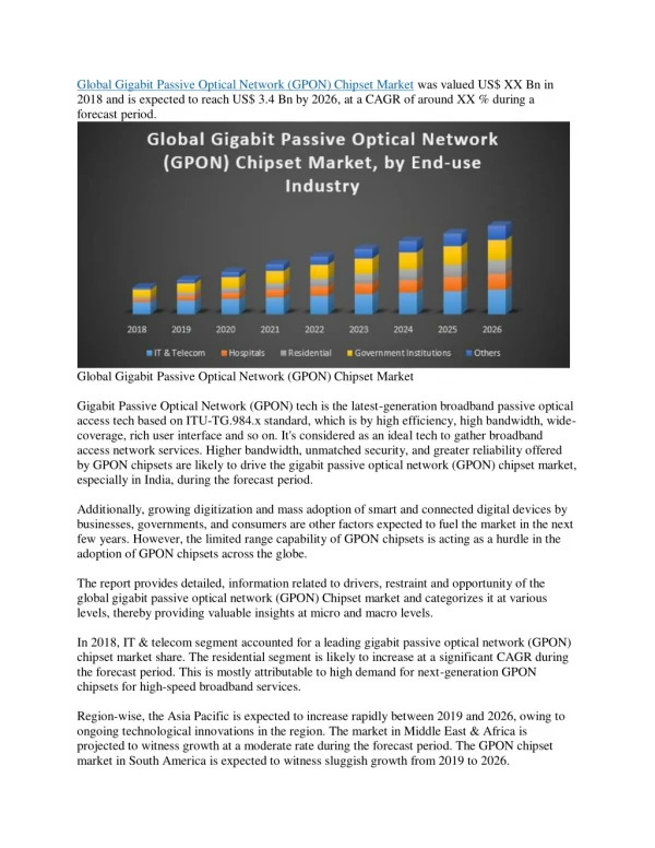
Passive Optical Network for TTC An investigation for TTC upgrade Sophie Baron, ACES2011
Upgrading the TTC PON basics First PON demonstrator for TTC Future Plans
The work presented here was conducted during 2009-2010 by Ioannis Papakonstantinou (Aceole Fellow), Csaba Soos (CERN/PH/ESE) and the Opto Team of PH/ESE/BE. (References at the end of this presentation)
Current TTC – Generic View Busy/throttle Busy/throttle Trigger unit TTCex 10 1 1 16/32 DAQ DAQ FE Controller FE driver FE driver TTCrx TTCrx TTCrx Counting room Detector Upgrading the TTC TTCrx TTCrx TTCrx Det. Module Det. Module Det. Module Det. Module Det. Module
Current TTC – Candidate for PON Busy/throttle Busy/throttle Trigger unit TTCex 10 1 1 16/32 DAQ DAQ FE Controller FE driver FE driver TTCrx TTCrx TTCrx Counting room Detector Upgrading the TTC TTCrx TTCrx TTCrx Det. Module Det. Module Det. Module Det. Module Det. Module
Upgrading the TTC A working group was settled between PH/ESE group and experiments‘ representatives in 2009 to: • Collect and discuss feedback on the current TTC system • Try to identify a common and preliminary set of requirements of an hypothetical new TTC • Investigate potential solutions (PH/ESE) • Report on investigations on a regular basis • Progress track is available here: http://indico.cern.ch/categoryDisplay.py?categId=2388 Upgrading the TTC
Basic Requirements • Common to all LHC experiments • Based on bi-directionality • Backward compatible with legacy TTC system • Flexibility in partitioning • Re-use of the current optical network would be a plus Upgrading the TTC
Bi-directionality • Downstream, broadcast/unicast: • Same requirements than for the TTC (BC, BCR, ECR, Calibration Pulses, etc) • Plus… • Even better recovered clock quality (<5ps rms) • 8 bit trigger type synchronous to the trigger • Higher bandwidth to allow more commands (region of interest readout, event routing information…) • Upstream: • Feedback and acknowledgment for control • Busy/throttle signals transmitted with short and bonded latency • Possibility to send latency controlled signals (calibration requests) • Fiber latency monitoring Upgrading the TTC
And here comes the PON… • Bidirectional • Current optical network: point to multipoint • Relatively high bandwidth downstream • Lower bandwidth upstream This is the typical topology of a PON system (Passive Optical Network), with some more constraints on clock recovery and fixed latency signals. We investigated this option in the framework of the ACEOLE/Marie Curie program at CERN. Upgrading the TTC
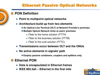
What is a PON? • Passive Optical Network • Alsocalled FTTH/B/C/x • Already mature technology • Natural evolution of the wirelinebroadbandmarket • Veryfastgrowingmarket (+20%/year in Asia-Pacific) • Estimation 170 Millions of subscribers in 2013 PON basics
What is a PON? • PON is a Passive Point-to-MultiPoint (PMP) optical network with no active elements in the signal path from the source to the destination • One single fibre in charge of both downstream and upstream transmissions • In the downstream direction (OLT→ONUs) PON is a broadcast network , using typically EPON (IEEE) or GPON (ITU) protocols • In the upstream direction (ONUs→OLT) a number of customers share the same transmission medium • Some channel arbitration mechanism should exist to avoid collisions and to distribute bandwidth fairly among ONUs • Several multiplexing schemes exist (TDMA, WDM, SCM, OCDMA..) FTTH FTTC TTCrx FEB TTCex TTCrx FTTB PON basics TTCrx
PON for TTC ** * * ** * TTCex FE interface/ TTCrx *: Splitters, OLT and ONU transceivers are COTS based on 1G-EPON First PON Demonstrator for TTC **: OLT and ONUs logic implemented in FPGAs
Hardware Demonstrator Implementation First PON Demonstrator for TTC
Downstream Frame • Raw rate 1.6Gbit/s • 590.8 Mb/s are available for data downstream, for example if broadcast only • 9.23 Mb/s per ONU (if 64 ONUs individually addressed) First PON Demonstrator for TTC
Upstream Frame • Technology choice: TDMA with 1G-EPON components • Splitting ratio: 1:N • 800MHz • ONU payload data = 4 bytes per turn • OLT training = 34 bytes • Inter Frame Gap (IFG) = 50ns min ONU laser turn-on ONU laser turn-off onu3 onu2 onu1 onu1 OLT training Payload IFG 9*25ns First PON Demonstrator for TTC Max busy/throttle latency for ONU1 = N*9*25ns N=64, latency = 14us N=8, latency = 2us
Demonstrator Performance CURRENT TTC AND PON-TTC DOWNSTREAM LATENCY CHARACTERISTICS PON-TTC Jitter characteristics First PON Demonstrator for TTC UPSTREAM LATENCY BREAKDOWN ANALYSIS
References • Passive Optical Networks in Particle Physics Experiments, Ioannis Papakonstantinou, 24th November 2009, PH-ESE Seminar • A Fully Bidirectional Optical Network with Latency Monitoring Capability for the Distribution of Timing-Trigger and Control Signals in High-Energy Physics Experiments, Ioannis Papakonstantinou et al., accepted for publication in IEEE TNS in 2011. Future Plans
Achievements • Successful proof of concept for a TTC upgrade • Bi-directionality with one fiber only • Much higher bandwidth • Compatible with legacy TTC • Excellent quality of the recovered clock • “Soft-partitioning” ... With the same optical infrastructure!! • And still many possibilities for improvement... Future Plans
Possible Future Developments • Reducing downstream and upstream latency • Using better PON technologies and faster FPGAs • Improving the protocol (currently simple proof-of-concept) • Fiber latency finding and monitoring at ONU level • Implement monitoring of both feeder and distribution fiber latencies, on an ONU per ONU basis (feeder fiber latency monitoring is already implemented). • Non-blocking fixed latency upstream architecture • Eliminate blocking time by using for instance spread spectrum technique like OCDMA. Typically, could support 64 users @ 10Mbps each (continuous & unshared!). • Overlaying wavelengths • Services could be added on-demand • Example: tri-band PONS • Reserve one wavelength for trigger only • Legacy TTC + PON TTC on a same network Future Plans
From TTC … Busy/throttle Busy/throttle Trigger unit TTCex 10 1 1 16/32 DAQ DAQ FE Controller FE driver FE driver TTCrx TTCrx TTCrx Counting room Detector TTC-PON at a glance TTCrx TTCrx TTCrx Det. Module Det. Module Det. Module Det. Module Det. Module
…To PON-TTC… Busy/throttle Trigger unit TTCex/OLT 10 1 1 16/32 DAQ DAQ FE driver FE driver FE Controller TTCrx ONU ONU Counting room Detector TTC-PON at a glance TTCrx TTCrx TTCrx Det. Module Det. Module Det. Module Det. Module Det. Module
Or even … Trigger unit OLT 10 1 1 16/32 DAQ DAQ DAQ GBT-FPGA FE driver GBT-FPGA ONU ONU ONU Counting room Detector TTC-PON at a glance TTCrx TTCrx TTCrx GBT GBT Det. Module Det. Module Det. Module GBT GBT
Downstream Frame • Raw rate 1.6Gbit/s • Synchronous transmission of super-frames with a period of 1625ns = 65*25ns at 1.6Gbit/s • 8b/10b encoding (1Field = 1 symbol) • 590.8 Mb/s are available for data downstream, for example if broadcast only • 9.23 Mb/s per ONU (if 64 ONUs individually addressed) First PON Demonstrator for TTC
Upstream Frame • Channel arbitration at the OLT (based on a simple round-robin scheme) • Slave N1 receives an R/F character with its address and switches its laser ON • IFG between successive emissions allows receiver to adapt between bursts • Long sequence of idle bytes for CDR & frame alignment • 4 bytes of payload • Total BW 800Mb/s • Latency not fixed but bonded • Optimized latencies with 1G-EPON components • if 64 ONUs: 14 us (BW/slave=2.2Mb/s) • If 32 ONUs: 7 us (BW/slave=4.5Mb/s) • If 8 ONUs: 2 us (BW/slave=18Mb/s) • … First PON Demonstrator for TTC ~300ns for highdynamic range systems (20dB) 50ns for low dynamic range (<6dB)
Demonstrator Performance CURRENT TTC AND PON-TTC DOWNSTREAM LATENCY CHARACTERISTICS PON-TTC Jitter characteristics Min Upstream Frame Duration Breakdown Analysis First PON Demonstrator for TTC
Latency monitoring Future Plans
Tri-band PON Future Plans
OLT implementation in Virtex5 simplified block diagram of OLT transmitter timing of frames before and after gear-box. gear-box operation Future Plans
ONU implementation in V5/Spartan6 Simplified block diagram of ONU receiver comma detect logic implementation timing of incoming frames relative to the two versions of the recovers 40 MHz clock. Future Plans
WDM technique OLT RN ONUs WDM Tx λ1 Receiver Band A SLED λ1 … λ1, λ2, … λ16 λ17 λ17, λ18, … λ32 RSOA 3 dB Coarse WDM λ17 CW 1 x 16 AWG WDM Rx … λ16 λ17, λ18, … λ32 Receiver Coarse WDM λ16 Modulated … λ32 Upstream band REAM Downstream band Coarse WDM Band B λ32 Receiver Array DEMUX λ Future Plans
OCDMA technique Frequency spreading Time spreading Future Plans