Download
1 / 26
260 likes | 273 Views
Developments for a passive optical node network for deployment in deep sea enabling time synchronous data readout. introduction on the PON (Passive Optical Network) Fiber span measurements for bidirectional data transport

E N D
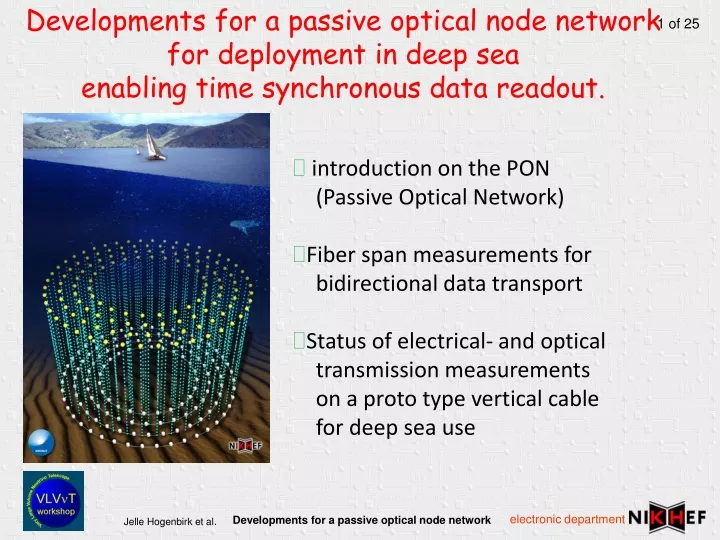
Developments for a passive optical node network for deployment in deep sea enabling time synchronous data readout. • introduction on the PON (Passive Optical Network) • Fiber span measurements for bidirectional data transport • Status of electrical- and optical transmission measurements on a proto type vertical cable for deep sea use
Passive optical node network CW Laser seed l’s DWDM om REAM System link for fiber length measurement only propagation measurement junction box receiver data collection vertical cable DWDM < 2000m ~ 100 km 1 wavelength from laser source modulated wavelength Pulse for fiber length measurement Control for fiber length measurement
Optical channels* enable synchronous readout or an optical node network • no data congestion in offshore system • reduced electronics on seabed • event clock value added to data on shore • embedded detector calibration features • embedded detector control (easy future detector upgrading, reduced power, early start of production,..) control also (or partially) possible over the power feed * An optical channel is one applicable wavelength in a DWDM system It is an optical point to point connection Today DWDM systems with 100 optical channels are used in standard telecom systems
An synchronous read out system CW lasers Seed l’s Add/drop mux l’s GPS OM 400V 3.3V control serialiser clock DAQ control, timing, calibration rec. REAM rec. rec. rec. rec. rec. rec. data DWDM PMT PMT PMT PMT PMT Power 10 kV shore 100km cable DWDM 2000 m 400 V 10kV 400V junction box
Fiber span measurements for bidirectional data transport
Bidirectional transmission test setup at the University of Eindhoven (NL) Conclusion: works good for 10Gb/s. within a span of 2000 m
Status in March 2008 of electrical- and optical transmission measurements on a proto type vertical cable for deep sea use Objective: Exploring electrical and optical behavior of the cable and connectors from atmospheric pressure to deep sea pressure up to 600 Bar (6000 m.) Unshielded Twisted Pair Transmission characteristics of UTP (cat5) in a silicone oil environment Electrical network analyzing Optical fiber: Corning SMF-128 (standard single mode fiberwith Draka Comteq pressure resistant coating) Optical attenuation @ 1310 and @1550 nm OTDR -- Optical Time Domain Reflectometry -- reflections and optical loss CD -- Chromatic Dispersion – on short cable minor influences compared to PMD PMD -- Polarization Mode Dispersion -- Mechanical behavior (pressure, torsion, bending etc.) using a Stimulated Brillouin OTDR
Seacon’s proto type cable and connectors 25 m. 25 m. 25 m. 25 m. 1.0 m 1.0 m 1.0 m Connector: 1 twisted pair cable 34 optical fibers Connector: 4 twisted pair cables 40 optical fibers Connectors 1 twisted pair cable 2 optical fibers
Network analyzing on the vertical cable • Measurements carried out by Peter Jansweijer and Henk Peek (Nikhef)
The current twisted pair in the proto type cable: Has Group Delay that is fine Has High Dielectric Loss Stubs must be terminated (extra electrical loss) Future improvements If possible use a different low loss silicone oil(e.g. transformer oil D = 0,0001) Avoid stubs Network analyzer conclusions
Cable test setup at Nikhef PMD analyzer Dark chamber for the multi PMD test setup Network analyzer OTDR Cable under test Fiber microscope PMD analyzer has been set to our disposal by EXFO
Optical Loop test setup -8.70 dB -10.26 dB -16.05 dB OTDR -7.50 dBm 15 7 8 9 10 11 12 13 14 7 8 9 10 11 12 13 14 15 light source -6.00 dBm -33.6 dB Rec. Open for OTDR Measurement +100m fiber Loop length ~3750 m (36 in the cable assembly and 2 m pigtail/fiber) Attenuation for total loop : 26.10 dB @ 1550nm (~40 dB @ 1310 nm) 144 connections average of ~ 0.2 dB loss per connection @ 1550 nm Optical loss per connection in calculations between 0.5 dB to 1.0 dB Deep sea connector Rec. source Loop connection 100 m. -6.00 dBm -7.50 dBm
Loop test OTDR value over 1000 m. 1.0 Km 5 dB/div. ~10 dB loss end of segment reflections on connectors 500 m/div.
PMD effects, general introduction Cross-section asymmetry Stress Torsion Temperature changes input output • Polarization Mode Dispersion is observed by a time delay between two orthogonal polarization modes • at the output of the fiber. • The PMD coefficient is expressed in ps/Ökm • A generally excepted rule: The absolute PMD value may not exceed 10% of a bit period over the entire fiber span (e.g. 10Gb/sec -> max PMD of 10ps)
Measuring PMD Measurements according to ITU specifications FOTP-24 (standard method fiber optic test procedure) EXFO PMD equipment measures according to FOTP-24a Corning optical cable SMF128 FOTP-24 scheme Intense in % Time psec.
PMD effects in the test cable 40 femto sec.
Test in the pressure vessel at NIOZ Light source -6dBm attenuation ~44 dB Attenuation over 120 connections < 0.3 dB/connection Pressure vessel spec’s: up to 600bar, Ø 0.80 meter, depth 1.80 meter NIOZ (Royal Netherlands Institute for Sea Research) Texel (NL)
OTDR result in pressure vessel all fibers ~ 3674 m atmospheric pressure Reflection in end faces of 3 connectors Attenuation (dB) Optical lossover 3 connections Optical lossover 3 connections recovers from a saturated reflection signal Fiber length Amplifier noise from OTDR
OTDR result in pressure vessel all fibers ~ 3674 m pressure 200 bar ~ 5 dB loss on connectors of fiber 16 to 17 No significant loss on the fiber at 200 bar
PMD mesurement result in pressure vessel all fibers ~ 3674 m pressure 200 bar 23 of 36 PMD: 0.0263 ps Coefficient: 0.0833 ps/km^1/2 Result: within specifications for 10Gb/s (10 psec)
PMD mesurement result in pressure vessel all fibers ~ 3674 m pressure 200 bar 24 of 36 PMD: 0.0233 ps Coefficient: 0.0110 ps/km^1/2 Result: within specifications for 10Gb/s (10 psec)
Conclusions on the optical measurements • Measurement: Optical attenuation increased with increasing pressure • Explanation: Head cable connectors showed serious leakage of oil into the dry part of the connector • No fiber pistoning, pinch or other jam measured • Measured values remained within the foreseen specifications Next steps: • After mechanical modifications of the connectors, optical measurements will be repeated. • Measurements with a stimulated Brillouin OTDR for precise measurement of mechanical stress in the fibers under pressure. • Further investigate the use of optical amplifiers
Joint efforts of: • KM3NeT teams of Nikhef (Amsterdam, NL) • Mechanical Workshop • Mechanical Engineering department • Electronic Technology department • CIP Center for Integrated Photonics (Ipswich, UK) • Seacon Europe (Great Yarmouth, UK) • NIOZ: Royal Netherlands Institute for Sea Research (NL) • VanderHoekPhotonics (Vlaardingen, NL) • Rood Engineering for the EXFO optical instruments (Rijswijk, NL) • Technical University of Eindhoven Cobra (Eindhoven, NL)