Download
1 / 7
70 likes | 196 Views
Digital Thermostat and Data Logger. Brandon Wagner and David Southwick. Schematic. ATmega88PA MAX232 Level Shifter 5V to 15V PCF8583 Real Time Clock LM34 precision Fahrenheit Sensor 10 mv / °F 24LC256 EEPROM 32K x 8 storage EVE-GA1F2012B Rotary Pulse Generator GDM1602K 2x16 LCD

E N D
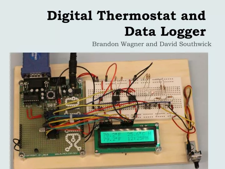
Digital Thermostat and Data Logger Brandon Wagner and David Southwick
Schematic • ATmega88PA • MAX232 Level Shifter • 5V to 15V • PCF8583 Real Time Clock • LM34 precision Fahrenheit Sensor • 10 mv/ °F • 24LC256 EEPROM • 32K x 8 storage • EVE-GA1F2012B Rotary Pulse Generator • GDM1602K 2x16 LCD • 2 LEDs • Pushbutton Switch I2C Serial CLK I2C Serial DATA ADC0 pin
Features • Current Time and Temperature display • Fahrenheit and Celsius • User selectable threshold temperature • 0.1° F precision via RPG rotation • Heating mode or A/C mode • H – Heating mode • Red LED active when temp below threshold • A – A/C mode • Green LED active when temp above threshold • Temperature data logger with time stamp • Stores temperature in EEPROM on a user selected interval • Serial interface to computer terminal • Commands: • “T” – Time change request • “D” – Date change request • “H” – Temperature history request • “C” – Change storage interval Actual Temp (F) Actual Temp (C) • Mode • Heat • A/C User Desired Temp Current Time
Temperature Logging Terminal - Enter “H” Import data to EXCEL Use EXCEL to plot Temp vs Time
Software • Initialize/Configure USART, LCD, I2C, ADC, and Timers • Determine RPG rotation • Increment or Decrement desired temperature setting • Check pushbutton • Toggle heat or A/C mode • Update LED outputs • If A/C mode: activate green LED if desired temp < actual temp • If heat mode: activate red LED if desired temp > actual temp • If (Timer0 flag set) – set every second • Read ADC register • Convert to value to Fahrenheit and Celsius • Read RTC for date and time • Update LCD with actual and desired temp, mode, and time • If (Timer1 flag set) – set every user defined number of minutes • Format temperature and time/date from RTC into a string • Write data string to EEPROM • Process any input from USART • “H” - Read data from EEPROM • “T”, “D” - Write to data to RTC
Analog to Digital Converter 1 1 0 0 0 0 0 0 ADC Channel Select = ADC0 VREF = Internal 1.1 V 1 1 0 1 1 1 1 0 ADC Enable Start Conversion Conversion Complete INT Flag Freq Prescaler: 50-200 kHz Choose 8MHz/128 = 125 kHz ADC INT Enable • Example: Temperature is 74.8 °F • => Sensor outputs 74.8 x 10 mV = 0.748 V Resolution = 1.1V / 1024 = 1.074 mV => ADC value of 1 = 1.074 mV • LM34 outputs 10 mv / °F Convert back to °F: 696.32 x 1.074 = 747.8 display “74.7°F”