Download
1 / 35
350 likes | 454 Views
CLIC potential baseline changes CTC items. H. Schmickler, G. Riddone - 11.12.2009. Conclusion taken from M.Jonker; last Friday (56 pages). The base line machine protection provides an adequate framework for protection against fast and slow failures.

E N D
CLIC potential baseline changes CTC items H. Schmickler, G. Riddone - 11.12.2009
Conclusiontaken from M.Jonker; last Friday (56 pages) The base line machine protection provides an adequate framework for protection against fast and slow failures. The large amount of time available between pulses allows an exhaustive post pulse analysis to authorize the next pulse. The challenging issues: mask and spoilers to • Intercept a single main bunch up to a full main train • intercept a “derailed” decelerator train. More info is needed to estimate consequences of RF failures. Kickers reliability to be looked into.
L*=3,5m and L*=6(8)m • Complicated optimization:Shorter L*= higher luminosity, easier insertion tuningLonger L* = lower luminosity, easier to achieve technical solution for vibration stability • Lots of progress in the past months on:- design of FF magnets- vibration measurements- studies on possibilities of active stabilization- physics detector size- knowledge on boundary conditions from experiments • Still it seems not possible to decide for a layout with convincing feasibility for the CDR now: Conclusion: Follow studies and designs for both optionsL*=3,5m and L*=6(8)m; Can we at least decide 6 or 8 or 6,42?
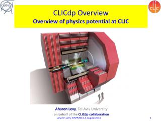
How does the cost of a klystrons scale with peak power? Erk Jensen (*) rule of thumb given by T. Habermann/CPI. Rees/LANL estimates P0.2 for 0.5 to 5 MW tubes. 07/Apr/2009 Probably: cost per klystron proportional to (peak power)1/2 (*) At a level of around 15 MW peak, the slope will become steeper due to increased system complexity. This leads to the following model: Blue: present state of the art Red: assuming a major investment into the development of a dedicated 30 MW tube CTC#13: Erk Jensen - RF system for the Drive Beam Linac 8
Cost per MW 07/Apr/2009 • Using the above model, here’s the klystron cost per MW (peak) • Blue: present state of the art • Red: assuming a major investment into the development of a dedicated 30 MW tube CTC#13: Erk Jensen - RF system for the Drive Beam Linac 9
Tube lifetime What about an MBK?: is the tube dead if one of n beams fails? If the design is good, the n beams would fail at around the same time ... 07/Apr/2009 In spite of its price, a klystron is a consumable! A klystron has a finite lifetime; this will also depend on its internal complexity (and on the peak power!). The lifetime will depend on many parameters, primarily the current density, but here’s one estimate ... CTC#13: Erk Jensen - RF system for the Drive Beam Linac 10
Cost for 100,000 operating hours and MW 07/Apr/2009 • Even if this model may be wrong, there will be a cost per MW and per operating hour: With the above model, this becomes: • Blue: present state of the art • Red: assuming a major investment into the development of a dedicated 30 MW tube CTC#13: Erk Jensen - RF system for the Drive Beam Linac 11
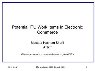
Pre-Injector e- Linac MKS 03 MKS 02 MKS 01 50 Hz 50 Hz 50 Hz 40 MW 40 MW 40 MW 2 GHz 2 GHz 2 GHz SLED SLED DC Gun A1 A2 A3 A4 B1 PB2 PB1 200 MeV 20 MeV • Accelerating cavities: • Number of cavities: N = 4 • Length: L = 3 m • Aperture radius: r = 20 mm • Energy Gain: DE = 45 MeV • Accelerat. gradient: Ez = 15 MV/m • Frequency: f = 2 GHz Louis Rinolfi
Erks optimization of the unit klystron power isbased on maintenance and reliability questions combined with lowest price/MW. • The optimization has been done for the DB linac, since there we have the largest klystron installation. • The base line change for the klystron power demands a reoptimization of the linac structures (#cells).This is almost done; base line change should be made. • The same logic should be applied for all other linacs (injectors, bunch compressors…). This also needs a (re)design of the connected RF-structures.
Background (1/2) • 4000 MB quads, need about 80 correctors close to quads for beam-based feedback (BBF); • Pre-choice of 80 locations impossible? equip all 4000 quads with correctors • Frequency range covered by BBF: sub-Hz to ~1 Hz • In order to - have some feedback gain at f_cl =1 Hz (f_cl = f_s/gain)- to average over several BPM readings the BBF will run at a sampling frequency f_s=50 Hz; i.e. the corrections are applied every pulse:requested settling time of corrections is 5 ms( in-between 2 beam pulses )
Background (2/2) • Technical implementation in 2008:- additional windings onto quad jokes in order to produce “a sort of dipole correction field” • Pre-Choice of non-laminated MB quads for stabilization and mechanical engineering (late 2008)excludes correction coil (bandwidth problem) • Present design approach: Extend dynamic range of stabilization actuators by 100 ! and make BBF corrections by displacing the MB quads.Fullscale = +- 5 um compared to +- 50nm
Problems with present implementation • Actuator dynamics, in particular for the (long) heavy magnets • Absolute position of quad in beam reference frame not know (Hexapod design with sub-nm position readout in each leg) • BPMs (50 nm required resolution) will move with quad.Needs sophisticated bookkeeping of past displacements.BPM close to “zero” and for longer elongations non-linear (monopole and quadrupole mode signals) • Machine protection: non-energized position of quad (vertical) is max.down, not middle; might need interlocks.
Implementation • Required corrector strength (Bdl):200 T/m *10 um * 2m (@ 1.5 TeV) = 4 mT * m = 0,4 T * 1 cm - very week magnetassumed strength: scales with length of Q corrector@ Q1: 0,1 mTm • 1 cm long 0.1 - 0.4 T magnets • - end-field problems?- interference with quad field?- will create synchrotron radiation?(200 times higher bending radius)
7 Dec. 09 : “CLIC Quadrupoles STATUS” at CLIC Module WG (M. Modena) 18
7 Dec. 09 : “CLIC Quadrupoles STATUS” at CLIC Module WG (M. Modena) 19
7 Dec. 09 : “CLIC Quadrupoles STATUS” at CLIC Module WG (M. Modena) 20
7 Dec. 09 : “CLIC Quadrupoles STATUS” at CLIC Module WG (M. Modena) 21
7 Dec. 09 : “CLIC Quadrupoles STATUS” at CLIC Module WG (M. Modena) 22
7 Dec. 09 : “CLIC Quadrupoles STATUS” at CLIC Module WG (M. Modena) 23
7 Dec. 09 : “CLIC Quadrupoles STATUS” at CLIC Module WG (M. Modena) 24
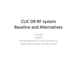
2 x 2000 MB-Qs 4 types (lengths) BPM on each Quaddipole corrector on each quad All MB-Qs need stabilization equipment: Postion sensors (v- sensors+ integration ora-sensors + double integration) Piezoelectrical actuators (presently hexapod design) MB-Q Stabilization WPS and HLS plus overlapping wires as reference Linear motors as actuators Prealignment Prealignment without beamWith beam: Beam based feedback (all BPMs + about 80 actuators) Quad Stabilization (sensors + actuators on each Quad) Controller – topology? Sensors and Actuators?
Pre-alignment:- overlapping stretched wires, WPS, HLS as baseline for CDR- linear actuators- continuing studies on laser systems (start with IP)and on camshaft movers- controller: local or central: decision not needed • Beam based feedback:- based on MB BPMs: open question for CDR:- online dispersion measurements by in-pulse energy variation or by pulse to pulse variation?- actuators: small dipole correctors- controller: First design needed for CDR • MB-Q stabilization- for CDR: sensors and actuators, independent (local) controllers interesting alternative to be studied: sensors as before, but common controller with BBF and small dipole correctors as actuators (“move the beam within a vibrating quadrupole rather than stabilizing the magnet”)
Cavity BPM spectrum calculation e- r HFSS EigenMode Calculation HFSS Data: W - Stored Energy P_coax - Exited RF Power Ez - E-field along bunch path gsym - Symmetry coefficient Scale Factor: Output Power: (II) Bunch trajectories (I) Matched Impedance, P_coax Estimated Sensitivity (q0 = 1nQ): V/nQ/mm
Taken from E.Adli’s presentation Choice not obvious: tradeoff between number of BPMs and precision; availibility, cost versus precision, risk….
BPM Mechanical Tolerances a) • There is no visual advantage of particular scheme of coaxial layout (a, b, c) • The most sensitive to mechanical errors part of the BPM is a coupling slot. • The required mechanical tolerances of a cavity with coupling slots: Port 2 Port 1 b) Port 3 Port 4 c) 1 - In-phase signals reflection (worse case) is taken into account. 2 – The reflection from LLRF part is assumed less than -20 dB.
Summary BPMs • MB: At each MB-Q Cavity BPMs (FNAL Design) with integrated reference cavity for intensity information.Small study needed for extra cost of double readout vs redundancy and on-line calibration benefits. • DB: Large number: at each DB quadtechnical choice of DB BPM: BI group + collaborators in 2010- compromise between cost reduction, extra effort for better alignment in case of reduction of BPMs etc not before CDR.
Color codes used = could be decided today = needs some work, decision before CDR writeup ..i.e. before summer 2010 = interesting alternative, decision not before CDR