Download
1 / 27
280 likes | 425 Views
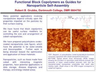
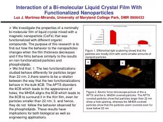
The Broader Approach Projects. P. Barabaschi F4E Garching – 14 Apr 2011. BA Agreement. JT-60SA. Together with IFERC and IFMIF-EVEDA, JT-60SA is part of the « Broader Approach » agreement signed between Euratom and Japan Entered into force in 2007. IFERC. IFMIF-EVEDA. IFMIF.

E N D
The Broader Approach Projects P. Barabaschi F4E Garching – 14 Apr 2011
BA Agreement JT-60SA Together with IFERC and IFMIF-EVEDA, JT-60SA is part of the « Broader Approach » agreement signed between Euratom and Japan Entered into force in 2007 IFERC IFMIF-EVEDA
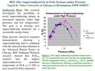
IFMIF IFMIF (international fusion materials irradiation facility) will be a neutron source based on a stripping reaction between two deuteron beams and a lithium target aimed to generate a fusion reactor relevant radiation environment with a high neutron flux Hence IFMIF will evaluate irradiation performance of the structural materials under fusion typical conditions -> needed for DEMO. Lithium Target 25±1 mm thick, 15 m/s MEBT LEBT HEBT Source 140 mA D+ Half Wave ResonatorSuperconducting Linac Accelerator(125 mAx 2) Test Cell RF Power System L M RFQ H 100 keV 5 MeV 9 14.5 26 40 MeV Beam shape: 200 x 50 mm2 High (>20 dpa/y, 0.5 L) Medium (>1 dpa/y, 6 L) Low (<1 dpa/y, > 8 L)
Current activities: IFMIF/EVEDA • The Engineering Validation and Engineering Design Activities, conducted in the framework of the Broader Approach aim at: • Providing the Engineering Design of IFMIF • Validating the key technologies, more particularly • The low energy part of the accelerator (very high intensity, D+ CW beam) • The lithium facility (flow, purity, diagnostics) • The high flux modules (temperature regulation, resistance to irradiation) • Strong priority has been put on Validation Activities, through • The Accelerator Prototype • The EVEDA Lithium Test Loop • Two complementary (temperature range) designs of High Flux Test Modules and a Creep fatigue Test Module
International Fusion Energy Research Centre Computer Simulation &Remote Experimentation Building Administration & Research Building DEMO R&D Building IFMIF/EVEDA Accelerator Building All buildings were completed in March 2010
Assembly of the EVEDA Lithium Test Loop Facility Building [40mW, 80mL, 33mH] JAEA Oarai • Commissioning undergoing • Successful operation at nominal temperature, nominal flow rate • Next step before experiment: check the velocity in the Target Assembly • Start of the experiments: June 2011 ELiTe Loop construction completed in November 2010
JT-60SA Objectives • A combined project of the ITER Satellite Tokamak Program of JA-EU (Broader Approach) and National Centralized Tokamak Program in Japan. • Contribute to the early realization of fusion energy by its exploitation to support the exploitation of ITER and research towards DEMO. ITER DEMO Complement ITER towards DEMO Support ITER JT-60SA
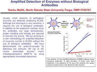
The New Load Assembly JT-60SA(A≥2.5,Ip=5.5 MA) ITER (A=3.1,15 MA) 3.0m 6.2m 1.1m SST-1 (A=5.5, 0.22 MA) 1.7m EAST (A=4.25,1 MA) 1.8m KSTAR (A=3.6, 2 MA) • JT60-U: Copper Coils (1600 T), Ip=4MA, Vp=80m3 • JT60-SA: SC Coils (400 T), Ip=5.5MA, Vp=135m3 JT-60U JT-60SA ~4m ~2.5m 8
Sharing CS, EF coils • Japan and EU implement in-kind contributions for components. • Existing JT-60U facilities will also be utilized. Power Supplies Compressor Building TF coils&Testing Water Cooling System NBI Cryogenic System ECRF Cryostat Diagnostics Vacuum Vessel In-vessel Components Assembly Remote Handling
High Beta and Long Pulse • JT-60SA is a fully superconducting tokamak capable of confining break-even equivalent class high-temperature deuterium plasmas (Ipmax=5.5 MA) lasting for a duration (typically 100s) longer than the timescales characterizing the key plasma processes, such as current diffusion and particle recycling. • JT-60SA should pursue full non-inductive steady-state operations with high N (> no-wall ideal MHD stability limits). 10
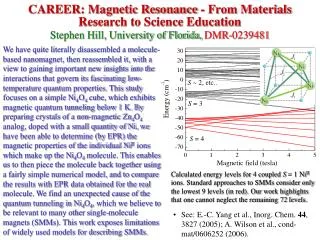
Plasma Shaping • JT-60SA will explore the plasma configuration optimization for ITER and DEMO with a wide range of the plasma shape including the shape of ITER, with the capability to produce both single and double null configurations. 11 Ip=5.5MA, Lower Single Null Ip=5.5MA, Double Null Ip=4.6 MA ITER like
Machine Parameters Cryostat P-NBI P-NBI ECH N-NBI • After successful completion of the re-baselining in late 2008, the JT-60SA project was launched with the new design with the following parameters. Basic machine parameters 12
Heating and CD Systems Variety of heating/current-drive/ momentum-input combinations NB: 34MWx100s Positive-ion-source NB 85keV 12units x 2MW=24MW COx2u, 4MW CTRx2u, 4MW Perpx8u, 16MW Negative-ion-source NB 500keV, 10MW for off-axis NBCD ECRF: 110GHz, 7MW x 100s 9 Gyrotrons, 4 Launchers with movable mirror 13
Magnet • All SC Magnet • 18 TF Coils • 6 EF Coils • 4 CS modules
TFC Procurement • Conductor Samples Tested successfully (1 from France , 1 from Italy) • Detailed Technical Specifications completed • Contracts for strand and conductor placed • Tenders for coils underway
TFC Cold Tests • All TFC will be cold (4.5K) tested at full current before shipping to Japan • Test Facility will be in CEA-Saclay • PA prepared with test facility specifications and cold testing specifications • HV Tests • Leak Tests • Flow, Pressure Drop • Dimensional Stability during and after cooldown • Resistance, Joints • Tmargin, Quench tests (2 coils) • Cryostat and jigs being fabricated. • Cryostat to be delivered in Saclay in first half 2011
PFC – on site manufacturing • Two buildings were constructed in Naka Site in 2009. Two large PF coils (EF-1&6 coils) of 12m in diameter will be manufactured in this building because they are too big to be transported by using public road. 680 m JT-60 (2) PF coil manufacturing building constructed in March 2009 Winding machine Cable spool area Jacketing line 12m (1) PF conductor manufacturing building constructed in March 2009 The first superconducting conductor of 450m for the EF-4 coil has been completed in March 2010. 18
Vacuum Vessel • Double Walled • 18mm+18mm • Boronised Water interspace (~160mm) • 200C Baking
Vacuum Vessel (2) • First Sector to be Delivered in mid March 2011 in Naka 20
MHD Control in-vessel components • Error Field Correction Coil (EFCC) • toroidal 6 x poloidal 2 coils (TBD) • 30kAT (TBD) • frequency ~100Hz (TBD) • RMP for ELM control • Fast Position Control Coil (FPCC) • upper and lower coils • 120kATurn • time response <10ms • VDE • RWM control Coil (RWMC) • toroidal 6 x poloidal 3 coils (TBD) • 20kAT (TBD) • Stabilizing Plate • SUS316L • Double Shell • VDE& RWM 21
Cryostat • Two parts (~650 Tonnes): • Main machine support • Cylindrical and lid • Procurement of Base started. Contract placed. Material procurement underway. Welding trials • First component to be installed in torus hall. Delivery in Naka planned for Mid 2012
Divertor Cassette Outer Baffle:0.3~1MW/m2 Bolted CFC and Graphite tiles Cover for Pipe Connection:0.3MW/m2 Bolted Graphite tiles exchanged by RH Outer target:1~10*MW/m2 Bolted CFC tiles exchanged by hand in hot-cell • CFC (type I and II) materials at the first stage were delivered at Naka in March 2009. • Development of the divertor target is in progress to examine brazing for the divertor target. Divertor cassette Outer target (40 degree):10~15MW/m2 CFC monoblock target • Fully water cooled PFC, in which CFC monoblock targets are partially installed. • Carbon tiles are bolted on cooled heat sinks. • RH compliant divertor cassette is adopted for future maintenance. 23
JT-60 Disassembly underway Mar. 2010 Neutron Shielding Wall High Voltage Deck of N-NBI Torus Hall Assembly Hall Sep. 2010 24
Phased Research Plan • Exploitation within the BA period will aim at the initial research phase: • - HH operation for plasma full commissioning • - DD operation for identification of the issues in preparation for full DD • operation • Principles of “Joint Exploitation” later phases agreed between EU and JA • Detailed “Research Plan” jointly prepared
Baseline Schedule • Start of Tokamak Assembly: Early 2012-Completion of Tokamak Assembly: October 2015-First Plasma: Mid 2016.
Conclusions • • The BA activities are underway since 3 years • IFERC: Supercomputer to start operation in 2012 • IFMIF/EVEDA: Prototype accelerator construction underway. Start of operations in 2014. IFMIF Design underway – intermediate report to be available in 2013 • JT-60SA: • rebaselining undergone in 2008 in order to reduce costs while maintaining its objectives • The procurement for the components has progressed with relevant contracts following the PAs for the supply of PF coils, vacuum vessel and divertor by Japan and power supply, cryostat, current leads and TF magnetby EU. The majority of the PAs are either signed or in final preparation • JT-60SA research plan has already started to be jointly developed between EU and JA for future exploitation in JT-60SA. Baseline schedule First Plasma in 2016 27