Download
1 / 38
400 likes | 453 Views
Chapter 13. Integration Testing. The Mars Climate Orbiter Mission. mission failed in September 1999 completed successful flight: 416,000,000 miles (665.600.600 km) 41 weeks flight duration lost at beginning of Mars orbit

E N D
Chapter 13 Integration Testing
The Mars Climate Orbiter Mission • mission failed in September 1999 • completed successful flight: 416,000,000 miles (665.600.600 km) • 41 weeks flight duration • lost at beginning of Mars orbit • An integration fault: Lockheed Martin used English units for acceleration calculations (pounds), and Jet Propulsion Laboratory used metric units (newtons). • NASA announced a US$ 50,000 project to discover how this happened.
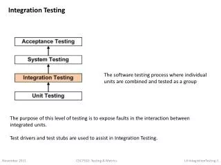
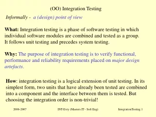
Goals/Purpose of Integration Testing • Presumes previously tested units • Not system testing • Tests functionality "between" unit andsystem levels • Basis for test case identification? • Emphasis shifts from “how to test” to “what to test” (Model-Based Testing)
Testing Level Assumptions and Objectives • Unit assumptions • All other units are correct • Compiles correctly • Integration assumptions • Unit testing complete • System assumptions • Integration testing complete • Tests occur at port boundary • Unit goals • Correct unit function • Coverage metrics satisfied • Integration goals • Interfaces correct • Correct function across units • Fault isolation support • System goals • Correct system functions • Non-functional requirements tested • Customer satisfaction.
Approaches to Integration Testing(“source” of test cases) • Functional Decomposition (most commonly described in the literature) • Top-down • Bottom-up • Sandwich • “Big bang” • Call graph • Pairwise integration • Neighborhood integration • Paths • MM-Paths • Atomic System Functions
Basis of Integration Testing Strategies • Functional Decomposition applies best to procedural code • Call Graph applies to both procedural and object-oriented code • MM-Paths apply to both procedural and object-oriented code
Continuing Example—Calendar Program • Date in the form mm, dd, yyyy • Calendar functions • the date of the next day (our old friend, NextDate) • the day of the week corresponding to the date • the zodiac sign of the date • the most recent year in which Memorial Day was celebrated on May 27 • the most recent Friday the Thirteenth
Calendar Program Units Main Calendar Function isLeap Procedure weekDay Procedure getDate Function isValidDate Function lastDayOfMonth Procedure getDigits Procedure memorialDay Function isMonday Procedure friday13th Function isFriday Procedure nextDate Procedure dayNumToDate Procedure zodiac
First Step in Top-Down Integration “Grey” units are stubs that return the correct values when referenced. This level checks the main program logic.
weekDayStub Procedure weekDayStub(mm, dd, yyyy, dayName)If ((mm = 10) AND (dd = 28) AND (yyyy = 2013)) Then dayName = “Monday”EndIf...If ((mm = 10) AND (dd = 30) AND (yyyy = 2013)) Then dayName = “Wednesday”EndIf
Next Three Steps (replace one stub at a time with the actual code.)
Top-Down Integration Mechanism • Breadth-first traversal of the functional decomposition tree. • First step: Check main program logic, with all called units replaced by stubs that always return correct values. • Move down one level • replace one stub at a time with actual code. • any fault must be in the newly integrated unit
Bottom-Up Integration Mechanism • Reverse of top-down integration • Start at leaves of the functional decomposition tree. • Driver units... • call next level unit • serve as a small test bed • “drive” the unit with inputs • drivers know expected outputs • As with top-down integration, one driver unit at a time is replaced with actual code. • Any fault is (most likely) in the newly integrated code.
Top-Down and Bottom-Up Integration • Both depend on throwaway code. • drivers are usually more complex than stubs • Both test just the interface between two units at a time. • In Bottom-Up integration, a driver might simply reuse unit level tests for the “lower” unit. • Fan-in and fan-out in the decomposition tree results in some redundancy.
Sandwich Integration • Avoids some of the repetition on both top-down and bottom-up integration. • Nicely understood as a depth-first traversal of the functional decomposition tree. • A “sandwich” is one path from the root to a leaf of the functional decomposition tree. • Reduces stub and driver development. • More complex fault isolation.
“Big Bang” Integration • No... • stubs • drivers • strategy • And very difficult fault isolation • (Named after one of the theories of the origin of the Universe) • This is the practice in an agile environment with a daily run of the project to that point.
Call Graph-Based Integration • Definition: The Call Graph of a program is a directed graph in which • nodes are units • edges correspond to actual program calls (or messages) • Call Graph Integration avoids the possibility of impossible edges in decomposition-based integration. • Can still use the notions of stubs and drivers. • Can still traverse the Call Graph in a top-down or bottom-up strategy.
Call Graph-Based Integration (continued) • Two strategies • Pair-wise integration • Neighborhood integration • Degrees of nodes in the Call Graph indicate integration sessions • isLeap and weekDay are each used by three units • Possible strategies • test high indegree nodes first, or at least, • pay special attention to “popular” nodes
Pair-Wise Integration • By definition, and edge in the Call Graph refers to an interface between the units that are the endpoints of the edge. • Every edge represents a pair of units to test. • Still might need stubs and drivers • Fault isolation is localized to the pair being integrated
Neighborhood Integration • The neighborhood (or radius 1) of a node in a graph is the set of nodes that are one edge away from the given node. • This can be extended to larger sets by choosing larger values for the radius. • Stub and driver effort is reduced.
Example of Neighborhood Integration Testing A A B E B C D E C D Total nodes = 5 Sink nodes = 4 Neighborhood = 5 - 4 = 1 Total nodes = 5 Sink nodes = 3 Neighborhood = 5 – 3 = 2 A A A B B E B C D E D C neighborhood(1) (1) neighborhood neighborhood (2)
How many neighborhoods are there? A D B C G E H F J I There are ( 10 nodes – 5 sink nodes) = 5 neighborhoods - 1 around the root (start here --- so there is some potential wait time) - 1 around B - 1 around E - 1 around C - 1 around D
Path-Based Integration Test • Instead of just focusing on the interfaces of the “related” modules in integration test, it would be more meaningful to also focus on the “interactions” among these related modules. • An extension of the neighborhood would be to trace a complete “thread” of interactions among the modules and test that “thread” or “path.”
Some Definitions for Path-based Integration Test • Source nodeis the point where program execution starts • Sink nodeis the point where the program execution stops • A module execution pathis a sequence of statements that begins with a source node and ends with a sink node, with no intervening sink nodes. • A message is a “mechanism” with which one unit of code transfers control to another unit of code; control return is also a message • An MM-path (module-to-module path) is an interleaved sequenceof i) module execution paths and ii) messages • Sequence of “nodes” represent a module execution path • Sequence of “edges” represent the messages • An MM-Path Graphis the directed graph in which nodes are from the module execution paths and edges are passing of control/messages.
MM-Path Definition and Example • An MM-Path is an interleaved sequence of module execution paths and messages. • An MM-Path across three units:
Exercise: List the source and sink nodes in the previous example.
Details of the Example MM-Path The node sequence in the example MM-Path is:<a1, a2, a3, a4> message msg1<b1, b2> message msg2<c1, c2, c4, c5, c6, c8, c9> msg2 return<b3, b4, (b2, b3, b4)*, b5> msg1 return<a6, a7, a8>Note: the (b2, b3, b4)* is the Kleene Star notation for repeated traversal of the loop.