Download

1 / 29
290 likes | 419 Views
MC Digi for Large Angle Vetoes. V. Palladino , T. Spadaro. MC Digi for Large Angle Vetoes. D etailed PMT simulation needed to assess efficiency @ low-energy Include and correctly treat: Gain fluctuations Optical g ’s path fluctuations Signal generation Time over threshold FEE.

E N D
MC Digi for Large Angle Vetoes V. Palladino, T. Spadaro
MC Digi for Large Angle Vetoes • Detailed PMT simulation needed to assess efficiency @ low-energy • Include and correctly treat: • Gain fluctuations • Optical g’s path fluctuations • Signal generation • Time over threshold FEE Signal (mV) N photo electrons 8.0 • MC input parameters: • Gain at operation point • G = 1.1 ×10⁶ • 1st dynode collection eff. • e1 = 0.85 • Intra-dynode collection eff. • ed = 0.98 • 1st dynode time fluctuations dT1 = 0.5 ns • Intra-dynode time fluctuations • dTd = 0.8 ns 6.4 4 4.8 3 3.2 2 1.6 1 Time (ns) Large Angle Veto WG meeting –Mainz – 6/9/2011 2
MC Digi: Data/MC agreement Data/MC agreement comparing MIP muons and using test beam data Further tests in progress Data MC Evts/0.5 pC Integrated charge (pC) Large Angle Veto WG meeting – Mainz – 6/9/2011 3
MC Digi: effect of cable Cable effect correctly reproduced in standalone simulation Whether or not it has to be inserted in official code is under scrutiny MIP signal Reminder, total cable length: small LAV’s: 6.15 m, 7.15 m, intermediate LAV’s: 8.5 m, big LAV’s: >~10 m Large Angle Veto WG meeting – Mainz – 6/9/2011 4
MC Digi: Data/MC agreement Data/MC comparing test beam data to MIP muons, varying (nominal) threshold for data For MC use: 290 pF PMT capacitance, 10 mV threshold, 3 mV hysteresis MC Data Integrated charge (pC) Time over threshold (ns) Large Angle Veto WG meeting – Mainz – 6/9/2011 5
MC Digi: Data/MC agreement For MC use: 290 pF PMT capacitance, 10 mV threshold, 3 mV hysteresis Data/MC agreement: looking in detail, not really satisfying MC Data Integrated charge (pC) Time over threshold (ns) Large Angle Veto WG meeting – Mainz – 6/9/2011 6
Characterization of ToT curve: CPMT For MC, study dependence of Q(ToT) on PMT capacitance MC, CPMT = 200 pF Integrated charge (pC) MC, CPMT = 300 pF MC default, CPMT = 250 pF, Vthr = 10 mV, Vhyst = 3 mV ToT (ns) Below ~ 8pC, leading time contribution significant For large signals, trailing time contribution dominates Large Angle Veto WG meeting – Mainz – 6/9/2011 7
Characterization of ToT curve: Vthr For MC, study dependence of Q(ToT) on FEE threshold voltage MC, Vthr = 11 mV Integrated charge (pC) MC, Vthr = 9 mV MC default, CPMT = 250 pF, Vthr = 10 mV, Vhyst = 3 mV ToT (ns) Uncertainty on nominal threshold, ~ 2mV Sizeable variation: dToT/dVthr ~ 3ns/mV, for low charges Large Angle Veto WG meeting – Mainz – 6/9/2011 8
Characterization of ToT curve: Vhyst For MC, study dependence of Q(ToT) on FEE hysteresis voltage MC, Vhyst = 2 mV Integrated charge (pC) MC, Vhyst = 4 mV MC default, CPMT = 250 pF, Vthr = 10 mV, Vhyst = 3 mV Hysteresis uncertainty ~ several % (to be confirmed) Acting on trailing time only: dToT/dVhyst ~ 1 ns/mV for low Q ToT (ns) Large Angle Veto WG meeting – Mainz – 6/9/2011 9
Direct measurement of CPMT Equivalent circuit for the direct measurement of CPMT = 33Ω Transmission line V(t) Rx PMT PMT Divider 33 Ohm resistor introduced to correct for parasitic inductance (ringing) Measure signal V(t) for Rx = 50, 100, 200Ω Fit the time constant t = CPMT (R + Rx) Large Angle Veto WG meeting – Mainz – 6/9/2011 10
Direct measurement of CPMT V(t) (mV/0.4 ns) Rx = 50 Ohm Fit with p0e-t/t time(s) Large Angle Veto WG meeting – Mainz – 6/9/2011 11
Data/MC agreement: old... For MC use: 157 pF PMT capacitance, take into account the 33 Ohm resistor, 9.5 mV threshold, 2 mV hysteresis Data/MC agreement: from the old situation.... MC Data Integrated charge (pC) Time over threshold (ns) Large Angle Veto WG meeting – Mainz – 6/9/2011 12
... and present For MC use: 157 pF PMT capacitance, take into account the 33 Ohm resistor, 9.5 mV threshold, 2 mV hysteresis Data/MC agreement: now much more satisfying MC Data Integrated charge (pC) Time over threshold (ns) Large Angle Veto WG meeting – Mainz – 6/9/2011 13
A first to-do list ToTvs Q curve well reproduced for MIP’s PMT capacitance value confirmed by direct measurement Quantitative check satisfactory Caveats: agreement for extremely low values of ToT to be studied Uncertainty on hysteresis to be determined Cable modifications treated: relevant for biggest LAV’s inserted into digitization code To-do list: check with electron data study of global LAV response new data acquisition campaign for better assessment of data/MC agreement to be tested with known threshold and hysteresis values Large Angle Veto WG meeting – Mainz – 6/9/2011 14
Precise threshold measurement Precisely assess threshold and hysteresis, mandatory for Q vs T reliability Sub-mV total uncertainty needed Tried with a standard approach, such as efficiency profile: measure efficiency as a function of minimum signal voltage Above approach would need clean environment: in presence of a 2-3 mV radiofrequency noise, width of efficiency profile depends on noise Try to overcome this, by measuring crossing times Large Angle Veto WG meeting – Mainz – 6/9/2011 15
Accurate mmt of threshold The idea is to register a signal copy and the LVDS output with a flash ADC The LVDS transition time, TL, can be correlated with the time TS(Vth) expected from signal, assuming a trial value Vth for the threshold As Vth varies, the correct threshold value is found as the one for which the time difference TL-TS is independent of the signal amplitude For this to work, the signal time characteristics have to be preserved as much as possible Large Angle Veto WG meeting – Mainz – 6/9/2011 16
Setup for threshold mmt Input to PMT from Hamamatsu C10196, ultrashort light pulser, 70 ps FWHM Large Angle Veto WG meeting – Mainz – 6/9/2011 17
Setup for threshold mmt Use LeCroyWaveSurfer 44Xs as 2.5 GS/s, 8-bit flash ADC Signal from DC 50 Ohm For the moment, an improper treatment of LVDS output: one polarity to signal, the other grounded via 100 Ohm resistor LVDS in Home made LVDS to LEMO Signal in Large Angle Veto WG meeting – Mainz – 6/9/2011 18
Problems for LVDS signal Due to this treatment, LVDS rise and fall times significantly worsened time over threshold possibly affected: 10-90% time to 1-1.5 ns but rise and fall time correlations expected to be maintained LVDS signal (V) Time (ns) Large Angle Veto WG meeting – Mainz – 6/9/2011 19
Time correlation measurements Leading time correlations as a function of trial threshold values For the true value of the threshold, dT should be independent from Vmin Vmin Thanks to Paolo Valente for the animated gif preparation dT (leading) (ns) Large Angle Veto WG meeting – Mainz – 6/9/2011 20
Time correlation measurements Rise time correlations as a function of trial threshold values For the true value of the threshold, dT should be independent from Vmin Vmin Thanks to Paolo Valente for the animated gif preparation dT (trailing) (ns) Large Angle Veto WG meeting – Mainz – 6/9/2011 21
Time correlation measurements Not exactly true... effect of overdrive-dependent delay at the comparator must be subtracted for dT to be independent on Vmax Reminder: for old (new) voltage at comparator is amplified x5 (x3) wrt original signal Large Angle Veto WG meeting – Mainz – 6/9/2011 22
Correlation factor Correlation factor well suited to evaluate “best” threshold value For leading time, method sensitivity is on the order of 0.2-mV Vle ~ -28.3 mV Correlation factor for leading times Vth(V) Large Angle Veto WG meeting – Mainz – 6/9/2011 23
Identification of optimal threshold: Correlation factor well suited to evaluate “best” threshold value For trailing time, method sensitivity is on the order of 0.1-mV Vth(trailing) ~ -30.7 Correlation factor for trailing times Vth(V) Large Angle Veto WG meeting – Mainz – 6/9/2011 24
Compare with efficiency profile Evaluation compared with that from efficiency profile e Vmin Large Angle Veto WG meeting – Mainz – 6/9/2011 25
Proposal for threshold validation Work shown able to clarify important points, but for en-mass mmts: To proceed in a reasonable time, need more channels TDC treatment of LVDS must be taken into account One may think: use a 32-channel, 5-GS/s, 8-bit flash-ADC with 1 Vpp at max Include in acquisition together with TDC Above approach would work for old FEE boards, in which each channel has an independent analog copy in output For new FEE’s, analog output are given for 4-fold and 16-fold sums only Proposed solution: pulse individual channels in a round-robin fashion can acquire with few channels of flash-ADC might exploit 4-ch, 12-bit, 2-GS/s V1729 digitizer, presently available Large Angle Veto WG meeting – Mainz – 6/9/2011 26
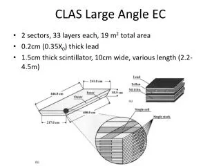
Logical scheme for fast simulation Particle generation and decay Interactions in LAV volume Energy release, Cerenkov • G4 Optical g’s: number, direction of emission, position • Mimmo’s transport matrix • Transport to the PMT • Number, energy of optical photons at PMT cathode • Photocathode emission • Dynode amplification • Signal generation • Transmission line • FEE: Threshold discrimination • This work • Leading and trailing times Large Angle Veto WG meeting – Mainz – 6/9/2011 S1 • ~10000 SF4 lead crystals • used in OPAL e.m. calorimeter • we re-use part of the barrel • 8 different crystal shapes • ρ=5.6 g/cm3, X0=1.5cm,RM=2.6 cm • Rearrange crystals in 4 or 5 staggered layers • Install rings inside vacuum vessel • ~10000 SF4 lead crystals • used in OPAL e.m. calorimeter • we re-use part of the barrel • 8 different crystal shapes • ρ=5.6 g/cm3, X0=1.5cm,RM=2.6 cm • Rearrange crystals in 4 or 5 staggered layers • Install rings inside vacuum vessel • ~10000 SF4 lead crystals • used in OPAL e.m. calorimeter • we re-use part of the barrel • 8 different crystal shapes • ρ=5.6 g/cm3, X0=1.5cm,RM=2.6 cm • Rearrange crystals in 4 or 5 staggered layers • Install rings inside vacuum vessel • ~10000 SF4 lead crystals • used in OPAL e.m. calorimeter • we re-use part of the barrel • 8 different crystal shapes • ρ=5.6 g/cm3, X0=1.5cm,RM=2.6 cm • Rearrange crystals in 4 or 5 staggered layers • Install rings inside vacuum vessel
MC Digi: effect of cable Cable induces RLC(G) filter C ~ 100 pF/m, L ~ 2.4 10-7 H/m Silver copper steel, R ~ 86Ω/km G varies withω, it is negligible for ω< 150 MHz, where signal lies x x + dx Attenuation |F(ω)| * cable data sheet, typical values for 30 m length ω (MHz) Large Angle Veto WG meeting – Mainz – 6/9/2011 S2
MC Digi: effect of cable Cable induces RLC(G) filter C ~ 100 pF/m, L ~ 2.4 10-7 H/m Silver copper steel, R ~ 0.086Ω/m G varies withω, it is negligible for ω< 150 MHz, where signal lies |F(ω)|, MIP signal Fourier transform ω (MHz) Large Angle Veto WG meeting – Mainz – 6/9/2011 S3