Download
1 / 18
190 likes | 380 Views
Chapter 5 Switch-Level Description. 4.1 Highlights of Switch-level Description. Switch-Level Description implements switches (transistors) to describe relatively small scale digital systems.

E N D
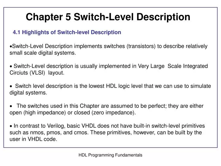
Chapter 5 Switch-Level Description 4.1 Highlights of Switch-level Description • Switch-Level Description implements switches (transistors) to describe relatively small scale digital systems. • Switch-Level description is usually implemented in Very Large Scale Integrated Circiuts (VLSI) layout. • Switch level description is the lowest HDL logic level that we can use to simulate digital systems. • The switches used in this Chapter are assumed to be perfect; they are either open (high impedance) or closed (zero impedance). • In contrast to Verilog, basic VHDL does not have built-in switch-level primitives such as nmos, pmos, and cmos. These primitives, however, can be built by the user in VHDL code. HDL Programming Fundamentals
NMOS switchPMOS switch nmos n1(drain, source, gate) pmos p1(drain, source, gate ) For strong output nmos should pull the output down to ground. For strong output pmos should pull the output up to vdd. HDL Programming Fundamentals
Gate 0 1 X Z • 0 Z 0 L L • Drain 1 Z 1 H H NMOS • X Z X X X • Z Z Z Z Z • Gate • 0 1 X Z • 0 0 Z L L • Drain 1 1 Z H H PMOS • X X Z X X • Z Z Z Z Z HDL Programming Fundamentals
5.3.2 VHDL Description of NMOS and PMOS Switches VHDL does not have built-in Primitives. WE can write a user defined primitives Listing 5.2 VHDL Code of NMOS and PMOS Switches as Components architecture nmos of mos is component nmos port (O1: out std_logic; I1, I2 : in std_logic); end component; component pmos port (O1: out std_logic ;I1, I2 : in std_logic); end component; for all: pmos use entity work. mos (pmos_behavioral); for all: nmos use entity work. mos (nmos_behavioral); HDL Programming Fundamentals
5.3.3 Serial and Parallel Combinations of Switches g1 g2 y 1 1 d 0 1 Z 1 0 Z 0 0 Z g1 g2 y 1 1 Z 0 1 Z 1 0 Z 0 0 d 2 nmos in serial 2 pmos in serial g1 g2 y 1 1 d 0 1 d 1 0 d 0 0 Z g1 g2 y 1 1 Z 0 1 d 1 0 d 0 0 d 2 nmos in parallel 2 pmos in parallel HDL Programming Fundamentals
Inverter with strong output And gate with degraded output pmos is pulling down to gnd and nmos pulling up to Vdd Listing 5.4 HDL Programming Fundamentals
Listing 5.5 2-input Or gate (degraded output) Listing 5.6 2-input NAND gate Listing 5.6 2-input NOR gate 5.5 Switch-Level Description of Simple Combinational Logics 2-input AND gate with strong output. Constructed from NAND and Inverter HDL Programming Fundamentals
Listing 5.9 2-input OR with strong output Listing 5.10 3-input NAND Listing 5.11 3-input NOR Example 5.10 y = Implementing NAND bates to express the function HDL Programming Fundamentals
By analyzing the function, we see that y is pulled to zero only if abc = 1 or if de =1 HDL Programming Fundamentals
Another XNOR listing 5.14 XNOR listing 5.13 Listing 5.15 2x1 MUX HDL Programming Fundamentals
5.6 Switch-Level Description of Simple Sequential Circuits SR-Latch as two NOR gates HDL Programming Fundamentals
5.6.1 CMOS Switches cmos (output, input, gn, gp) Listing 5.17 VHDL Code for CMOS Switch (Figure 5.19). library IEEE; use IEEE.STD_LOGIC_1164.ALL; entity CMOS is port (output : out std_logic; input, gn, gp : in std_logic); end CMOS; architecture macro of CMOS is -- All switches presented here do not include any time parameters such as --rise time and fall time. They only mimic the logical function of their --Verilog counterpart. component nmos port (O1: out std_logic; I1, I2 : in std_logic); end component; component pmos port (O1: out std_logic ;I1, I2 : in std_logic); end component; for all: pmos use entity work. mos (pmos_behavioral); for all: nmos use entity work. mos (nmos_behavioral); begin n1: nmos port map (output, input, gn); p1: pmos port map (output, input, gp); end macro; HDL Programming Fundamentals
Switch-level logic diagram of a D-Latch using pmos and nmos switches = Q is the inverse of HDL Programming Fundamentals
b) Switch-level logic diagram of a D-Latch using cmos switches E is high, C1 is closed, C2 is opened. Q follows D. E is low, C1 is closed, C2 is opened, Q retains its value HDL Programming Fundamentals
a) VHDL DescriptionD-latch using CMOS Switches library IEEE; use IEEE.STD_LOGIC_1164.ALL; entity D_Latch is port ( D, E : in std_logic; Q, Qbar : inout std_logic); -- Referring to Figure 5.22, signal Q is input and output and has multiple sources (the inverter and the CMOS switche, so Q has to be declared as inout. We also adjust all other ports in the following components to be inout. end D_Latch; architecture DlatchCmos of D_Latch is component CMOS port (output : out std_logic; input, gn, gp : in std_logic); end component; component invert Port (y : out std_logic; a: in std_logic ); end component; for all: CMOS use entity work. CMOS (macro); for all : invert use entity work.inverter(Invert_switch); signal Ebar, s1: std_logic; begin c1: cmos port map (s1, D, E, Ebar); c2: cmos port map (s1, Q, Ebar, E); inv1: invert port map (Ebar, E); inv2: invert port map (Q, Qbar); inv3: invert port map ( Qbar, s1); end DlatchCmos; Please correct Listing 5.19 To match the code shown here HDL Programming Fundamentals
b) Verilog Description, D-latch using CMOS Switches module D_latch(D, E, Q, Qbar); input D, E; output Q, Qbar; wire S1; cmos (S1, D, E, Ebar); cmos (S1, Q, Ebar, E); invert inv1(Ebar, E); invert inv2(Q, Qbar); invert inv3( Qbar, S1); endmodule module invert(y,a); input a; output y; supply1 vdd; supply0 gnd; pmos p1(y, vdd, a); nmos n1(y, gnd, a); endmodule Please correct Listing 5.19 To match the code shown here HDL Programming Fundamentals
5.7 Bidirectional Switches tran (dataio1, dataio2); trannif0 (dataio1, dataio2, control); tranif1 (dataio1, dataio2, control); HDL Programming Fundamentals
Summary of Verilog switches Verilog SwitchBrief explanation nmos n1(drain, source, gate); If gate =1, then source = drain, otherwise open (high impedance) pmos n1(drain, source, gate); If gate =0, then source = drain, otherwise open (high impedance) cmos (output, input, gn, gp); gp is the complement of gn. If gn =1, output = input, otherwise the switch is open (high impedance) tran (dataio1, dataio2); The switch always closed; it acts as a buffer; output = input. trannif0 (dataio1, dataio2, control); Bidirectional switches. If control=0, then dataio1 = dataio2; otherwise the switch is open (high impedance). tranif1 (dataio1, dataio2, control); Bidirectional switches. If control=1, then dataio1 = dataio2; otherwise the switch is open (high impedance). HDL Programming Fundamentals