Download

1 / 10
100 likes | 228 Views
NSTX. Supported by. Structural Analysis of PF1 , TF and OH Bus Bars NSTX-CALC--55-01-00 Scenario 72 Results. Andrei Khodak. Scenario 72 Results. Table 2. Table 4 Magnetic field source element properties. Scenario 72 conditions. Scenario 72 Results. Table 2. Bus Bar Temperature.

E N D
NSTX Supported by Structural Analysis of PF1, TF and OH Bus Bars NSTX-CALC--55-01-00 Scenario 72 Results Andrei Khodak
Scenario 72 Results Table 2 Table 4 Magnetic field source element properties Scenario 72 conditions
Scenario 72 Results Table 2 Bus Bar Temperature
Scenario 72 Results Bus Bar Temperature
Scenario 72 Results PF1B upper bus bar Repulsion of the bus bars leads to gap of 0.03m more than 1 inch
Scenario 72 Results PF1B upper bus bar Results for PF1 bus bars show that maximum values of stresses occur in flags where flags are connected to coil winding. Brackets connecting flags to coil insulation are proposed to improve strength of the connection. Introducing such brackets and/or extending G10 to the flags will eliminate narrow cross-section and improve stress situation Maximum stress is Near Flags
Scenario 72 Results Even without flags stress levels in PF1 bus bars are significant. To reduce the level of stresses clamping of the in and out bus bar together will reduce the deformation and corresponding stress levels at the supports. PF1C upper bus bar PF1A lower bus bar
Scenario 72 Results TF bus bar Prolong unsupported sections of the TF bus bar experience strong deformation due to magnetic forces. Peak value of deformation is 0.0106m
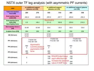
Scenario 72 Results TF bus bar Maximum value of stress intensity in the TF bus bar occurs in flag attached to the outer leg. High value of the stress is caused by thermal expansion of the bus bar, fixed between the outer leg and the floor. Compensation measures for thermal expansion are recommended for this portion of the TF bus bar. Peak stress intensity value is 1111MPa. Heat transfer analysis showed excessive temperature levels of 215ºC in the section of with a single conductor which is not cooled internally. Increase of the bus bar cross section is recommended in this area
Scenario 72 Results OH bus bar Maximum value of stress intensity in the OH bus bar occurs at the supporting bracket. Peak stress intensity value is 960MPa.